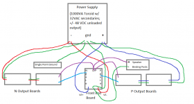
So signal comes into the front end board, (don't forget the "link", G to Link that is???), goes out through the "gate"conns, to the P channel/N channel boards respectively, in daisy chain, then comes back to the front end board and then to speaker binding posts? Should there be a purple line for the O/P joining the two P-channel and N-channels in your drawing?
Use the extra PCB for some kind of preamp...
The Output boards just daisy-chain together, the connections are clearly marked.
That's the Cyan lines - because the O/P is different from the N gates and P gates.
The Output boards just daisy-chain together, the connections are clearly marked.
Should there be a purple line for the O/P joining the two P-channel and N-channels in your drawing?
That's the Cyan lines - because the O/P is different from the N gates and P gates.
Last edited:
Agree - there should be cyan lines between the two output boards, so the second set of output fets.
Cyan is for gates...so on either side say the P-channel for example, the two p-channel boards are connected +Ve to +Ve, ground to ground and gate to gate but NOT O/P to O/P---no purple lines between two identical boards...?
I've been able to fix the soft start board the next day it smoked. RINNAV sent me to the right direction, I did not remember when I soldered the circuit because I ordered the part over 6 months ago and I ordered 0.33 uF for C9 instead of 1 uF... 😱 I've been listening to the amps for the last 4 days in my mains system. I'm very happy about the sound. This is a keeper. Nice soundstage, amazing bass and very good musicality. 🙂
Thanks Mr Pass for sharing your designs and everybody who helped me directly or indirectly by answering my questions or posted on this very helpful thread.
Cheers! 🙂
Cheers! 🙂
petefrontiers: yes, this is what I "figured" it would be, but my "figuring" has been amiss before.
In your picture the top row of boards would be N-channel (they look like they are all P-channel) and you have pictured one side (say the left side/channel) correct? Mirror this on the other side?
Hey I am very glad your amp has come together! I am spending much more time in preparation for this build than I usually do and that's a good thing 😱
This time I am checking Everything before I start; a lesson in humility 😡
I can't believe how I have missed details I thought I had under control 🙄
Thank you for your diagram! 😀
jdg123;3794361In your picture the top row of boards would be N-channel (they look like they are all P-channel) and you have pictured one side (say the left side/channel) correct? Mirror this on the other side? [/QUOTE said:On the picture, it seems everything is ok. The N channels are on the top row and connected to the output N channel of the front end board. I guess yes, you do the samething (mirror) for the right channel.
I've been able to fix the soft start board the next day it smoked. RINNAV sent me to the right direction...
Glad it work out for you! How do you think it was the first thing that I thought of? Except, with mine I noticed it when I was testing the soft start and PSU... 😉
@ jdg123 Here is a diagram that I found even on this thread for what you want to do.
My apology if I am repeating the question again:
1)where to connect the ground for the input signal at the input board?
2)what is the difference between the LINK and GND connection points at the
input board? Seems to me both are ground points to the output boards (one
for the P and one for the N board)?
3)The output from the P & N output boards (last output boards for the 4 pair
devices) are connected together at the +ve terminal of the speaker?
4)Any suggestion whcih ground point should the -ve terminal of the speaker
connects to?
Thank you very much!!
Regards,
Lo_Tse, at the far left side of the picture petefronteres sent are thin red lines indicating the connection to the speaker terminal 🙂
I had to download the file and enlarge it a bunch on my computer to see everything (sorry petefronteres, about my false ID of the upper row ) but if you do the same: download and enlargement you'll see more detail 😛
I'm pretty sure the Ground next to the IN on the front end board is supposed to connect to the "link" and that either the "link" or the ground then can act at the ground for the incoming signal...but I like to have a confirmation on that just like you 😱 I have made too many mistakes based on assumption
Cheers!
...and thanks for walking us through our questions you more experienced fellows! 😎
I had to download the file and enlarge it a bunch on my computer to see everything (sorry petefronteres, about my false ID of the upper row
) but if you do the same: download and enlargement you'll see more detail 😛I'm pretty sure the Ground next to the IN on the front end board is supposed to connect to the "link" and that either the "link" or the ground then can act at the ground for the incoming signal...but I like to have a confirmation on that just like you 😱 I have made too many mistakes based on assumption
Cheers!
...and thanks for walking us through our questions you more experienced fellows! 😎
My apology if I am repeating the question again:
1)where to connect the ground for the input signal at the input board?
2)what is the difference between the LINK and GND connection points at the
input board? Seems to me both are ground points to the output boards (one
for the P and one for the N board)?
3)The output from the P & N output boards (last output boards for the 4 pair
devices) are connected together at the +ve terminal of the speaker?
4)Any suggestion whcih ground point should the -ve terminal of the speaker
connects to?
Thank you very much!!
Regards,
1-2 : Link and ground are the same, Link has to be conected to ground by someway. I did it behind the board. I read before than Link is only used differently if you have balanced inputs. 3 - Yes, you connect all O/P all togheter, it doesn't matter where you choose to connect V+ to speaker, I connected it from FE boards but it could be connected from a N channel or a P channel's board as well. 4 - I connected speaker ground on FE board ( Link or Ground) It is like a star ground on FE board for RCA input and speaker VE-. Then the Fe board is connected to the audio star ground.
Hi all,
I want build a dual mono version of F5 Turbo V2. I'll use two 400VA transformers.
Do you think I'll need a soft start module? What about on speaker protection?
Thanks!
I want build a dual mono version of F5 Turbo V2. I'll use two 400VA transformers.
Do you think I'll need a soft start module? What about on speaker protection?
Thanks!
A soft start with TWO outputs. One output for each transformer.
The maximum output power from each transformer will be ~40W to 67W.
Is that what you are expecting?
The maximum output power from each transformer will be ~40W to 67W.
Is that what you are expecting?
Do you think I'll need a soft start module? What about on speaker protection?
I built the F5T v2 with 2 600VA trasformer and I use 2 softstart and 2 speaker protection modules. Both from DIYAudio store.
I think that you must have both of them
Enrico
Lo_Tse, at the far left side of the picture petefronteres sent are thin red lines indicating the connection to the speaker terminal 🙂
I had to download the file and enlarge it a bunch on my computer to see everything (sorry petefronteres, about my false ID of the upper row
I'm pretty sure the Ground next to the IN on the front end board is supposed to connect to the "link" and that either the "link" or the ground then can act at the ground for the incoming signal...but I like to have a confirmation on that just like you 😱 I have made too many mistakes based on assumption
Cheers!
...and thanks for walking us through our questions you more experienced fellows! 😎
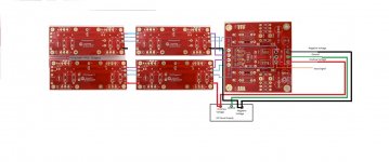
Thanks! Yeah, I save the picture already. May need to use a magnifying glass to trace the links on the board 😛
1-2 : Link and ground are the same, Link has to be conected to ground by someway. I did it behind the board. I read before than Link is only used differently if you have balanced inputs. 3 - Yes, you connect all O/P all togheter, it doesn't matter where you choose to connect V+ to speaker, I connected it from FE boards but it could be connected from a N channel or a P channel's board as well. 4 - I connected speaker ground on FE board ( Link or Ground) It is like a star ground on FE board for RCA input and speaker VE-. Then the Fe board is connected to the audio star ground.
petefrontiers,
Thank you for the detailed description. When I finish assembling the boards, I will re-read your notes and the photo that you uploaded.
Cheers!
Regards,
- Home
- Amplifiers
- Pass Labs
- F5 Turbo Builders Thread