Ahh ok thanks.
So if the OP here is running 45V rails then the Voltage over those feedback resistors would be 22.5V which through Ohms law should only have a max power of 4.22 watts with the 120ohm resistors.
So unless the heatsink wasn't touching the resistor at all, I'm sure that those MP915 should handle 4-5 watts with no problem.
Perhaps something else happened to cause those resistors to fail?
Ahh ok thanks.
So if the OP here is running 45V rails then the Voltage over those feedback resistors would be 22.5V which through Ohms law should only have a max power of 4.22 watts with the 120ohm resistors.
So unless the heatsink wasn't touching the resistor at all, I'm sure that those MP915 should handle 4-5 watts with no problem.
Perhaps something else happened to cause those resistors to fail?
Post #53 says 1.5W with no heatsink.
Post #53 says 1.5W with no heatsink.
yes but I think he was using a heatsink albiet a small one. So unless it was not touching at all I'm pretty sure 4 - 5 watts should be no problem.
Also 4-5 W rating is if he were to drive the amp right up to full rail voltage all the time!
1.5W rating for a non-heatsinked resistor would mean that he would need to output OVER 27V to his speakers for a extended period of time to blow those resistors! Thats like having a concert level listening session !!!!
Perhaps when he shorted ground it also affect the other amp? That and shorting the speaker terminals or using very inefficient speakers would be the only way I can see it possible to put enough voltage through the feedback loop to burn up those resistors.
Last edited:
Initial testing of the amp on the bench without a set of speakers or load would still put the same amount of stress on the feedback resistors. The damage to those resistors could have occurred while the amp was being constructed if a high enough level input signal was sent to the amp.
Ohm's law is about ohms, it's not about power.Ahh ok thanks.
So if the OP here is running 45V rails then the Voltage over those feedback resistors would be 22.5V which through Ohms law should only have a max power of 4.22 watts with the 120ohm resistors.
So unless the heatsink wasn't touching the resistor at all, I'm sure that those MP915 should handle 4-5 watts with no problem.
Perhaps something else happened to cause those resistors to fail?
The current through a resistance varies proportionately with the voltage drive.
I=V/R, or V=IR, or R=V/I
Are these the resistors you are asking about?Ahh ok thanks.
So if the OP here is running 45V rails then the Voltage over those feedback resistors would be 22.5V which through Ohms law should only have a max power of 4.22 watts with the 120ohm resistors.
So unless the heatsink wasn't touching the resistor at all, I'm sure that those MP915 should handle 4-5 watts with no problem.
Perhaps something else happened to cause those resistors to fail?
Anyways in my build I deliberately put 200R resistors in the feedback loop instead of the spec'd 110R in order to give 6dB more gain. I've had no problems with the resistor melting. Its been running continously for 8 months now with 50V rails
I don't know where the ½voltage came from. That sounds like bad advice.
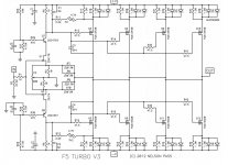
tell me on which exact schmtc to look , and I'll explain how's there half amplitude on feedback resistors , using proper designation numbers
Same schema from article.
I was thinking the same. The heat sink as it was attached should have had some effect. The destruction of the output stage in combination with testing practices and lack of proper heat sinking could all have contributed to the degradation of the resistors. Failure did not come from one issue/mistake/problem.
Can a resistor meant to be used with a heat sink suffer the same hot spots that a transistor can suffer if the case is not properly affixed to a heat sink? I think it might.
yes but I think he was using a heatsink albiet a small one. So unless it was not touching at all I'm pretty sure 4 - 5 watts should be no problem.
I was thinking the same. The heat sink as it was attached should have had some effect. The destruction of the output stage in combination with testing practices and lack of proper heat sinking could all have contributed to the degradation of the resistors. Failure did not come from one issue/mistake/problem.
Can a resistor meant to be used with a heat sink suffer the same hot spots that a transistor can suffer if the case is not properly affixed to a heat sink? I think it might.
Same schema from article.
.....
OK , V3 from article - attached
say , for simplicity sake , that we have +/-50V supply
then say that , for simplicity sake not counting on losses through mosfets and MURs , we have output amplitude of +/-50Vpp , which is exactly 100Vpp
then - we are looking at one feedback net half - say upper one , comprised of ((R7//R8)+R3)=120R
so , ref. to GND (where R3 is having anchored one leg) voltage at output node (other side of feedback net) is either +50Vpp or -50Vpp , which is nothing else than half output amplitude
so , current trough feedback net is 50Vpp/120R =416mA
lets put pause there ....... if you want dissipation on resistor expressed in normal way , we need to convert Upp to Urms , simply dividing Upp with 2 and again with sq. root of 2 , so 50/2/1.41 = 17V68
OK - current through feedback net is effectively (meaning - same as that DC voltage s there ) 17V68/120R=147mA
dissipation (P=I^2 x R) at R3 is 217mW
dissipation at R7 is 1.19W (half of 147mA !)
dissipation at R8 is 1.19W (half of 147mA !)
same applies on lower feedback net ((R9//R10)+R4)
to repeat - House : Everybody lies ...... either heatsink lied , or thermal goo lied or lied one who said it was heatsink there

so - don't bother what went wrong , just be sure that you have now properly heatsinked resistors ........
Attachments
Last edited:
to repeat - House : Everybody lies ...... either heatsink lied , or thermal goo lied or lied one who said it was heatsink there
I know what you are saying and I know what you mean by "lied", but we are being so honest about the mistakes that's it's a bit embarrassing. I misses queues from problems as I was looking at them, because I assumed too much instead of questioning what was in my gut. I assumed. Assuming makes an a** out of u and me. When I say "You", I don't mean you specifically. Focus is on "me". You see what I'm saying?
Thanks for the great explanation! 😀
when you're doing service work , there is distinct type of causes which can be only categorized in Twilight Zone
after some time (mileage) you're having enough of it , so caring (**thoroughly!) only for now and further , not what the hell happened
** making all (and stress) tests , to dismiss possible partially damaged parts
so - Everybody lies....... meaning primary on - my mind is playing games with me ........ I'll never fix that amp if I proceed thinking what went wrong ........ read this for more about scientific approach and possible never-ending loops
Last edited:
Folks:
Zen Mod's assessment is, as usual, quite right. In this case, it is entirely possible that some embarrassing mistake on my part caused the early demise of the MP915 resistors. And as Vince aptly noted, he and I have been brutally honest about the mistakes made (in fairness to Vince, the vast majority of the errors were unquestionably mine). But I would like to recover a little dignity; attached is a photo of the heatsink used with each MP915 resistor. I'll leave it to someone with a datasheet to decide if that heatsink is large enough to raise the dissipation to 4 to 5 watts. In the meantime, I've replaced each of those resistors with two 220R/3 watt Vishays, and I'll be listening to my F5T V3 amps, which are now back online.
Thank you to everyone -- Vince especially -- for all of the advice and assistance! I've said it before but it bears repeating: my skills, while slowly improving, are still feeble. Your insights, guidance and occasional assistance are critical elements in my success, and I really do appreciate the help.
Happy listening,
Scott
Attachments
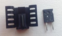
Looks like a 25deg C/W rated heatsink based on the data on this Mouser catalog page. This rating would of course assume that thermal paste was present. It would seem to me that this should be a sufficiently sized heatsink for the job.
I wouldn't worry too much about any mistakes, we ALL make them. This is DIY audio BTW and most of us are not audio experts, just audio hobbiest's. To be honest even experts make mistakes, IMO anyone that says they never make a mistake is not to be trusted. So mistakes are going to happen and are a part of the learning process. I should know as I make more than my fair share of them. 😀
I wouldn't worry too much about any mistakes, we ALL make them. This is DIY audio BTW and most of us are not audio experts, just audio hobbiest's. To be honest even experts make mistakes, IMO anyone that says they never make a mistake is not to be trusted. So mistakes are going to happen and are a part of the learning process. I should know as I make more than my fair share of them. 😀
I'm mistakeless!
except sole one - it would be better that I stayed in Paris , working as hooker , instead making my living from electronic
except sole one - it would be better that I stayed in Paris , working as hooker , instead making my living from electronic
Thanks ZM for clarifying the math. Makes sense.
Also good to note adding thermal grease to those little heatsinks.
Also good to note adding thermal grease to those little heatsinks.
Thanks ZM for clarifying the math. Makes sense.
Also good to note adding thermal grease to those little heatsinks.
Also good to note adding thermal grease to those little heatsinks.
- Status
- Not open for further replies.
- Home
- Amplifiers
- Pass Labs
- F5 Turbo 3 Failure