two adjustments, one for the bias current, and one for the DC output offset.
Two adjustments: One for the bias in the upper half, and one for the bias in the lower half.
Plus current sharing ratio - So three in total ?Two adjustments: One for the bias in the upper half, and one for the bias in the lower half.
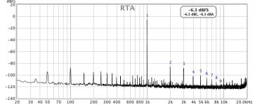
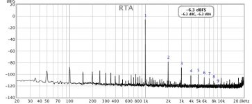
Has anybody tried to tweak F5 with P3 so its spectrum of distortion at 1 W is like this of F7
with 10 dB between 2nd and 3rd harmonic?
The distortion harmonics of my F5 with P3 at the middle position look like this:

with 10 dB between 2nd and 3rd harmonic?
The distortion harmonics of my F5 with P3 at the middle position look like this:
Has anyone built a version of the F5 with +/- 30V and 1A bias ?
Even better if you have made comparisons with the regular +/- 23V 1.3A version.
If so would like to hear your impressions
thanks
Even better if you have made comparisons with the regular +/- 23V 1.3A version.
If so would like to hear your impressions
thanks
I just built an F5 with a +/-30V SMPS in a bit smallish heatsink / chassis. I lowered the bias to .40v across the .47ohm resistors, so not quite 1A. Heatsinks measure at 130 - 135F. Left it there - perfect.
So I guess I am lower on total available wattage in Class A, but higher in available wattage in Class A/B? Either way, I like it!
So I guess I am lower on total available wattage in Class A, but higher in available wattage in Class A/B? Either way, I like it!
Sounds good - thanksI just built an F5 with a +/-30V SMPS in a bit smallish heatsink / chassis. I lowered the bias to .40v across the .47ohm resistors, so not quite 1A. Heatsinks measure at 130 - 135F. Left it there - perfect.
So I guess I am lower on total available wattage in Class A, but higher in available wattage in Class A/B? Either way, I like it!
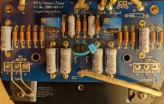
I'm playing around with a fan cooled F5 at the moment but running into bias problems. I'm using cviller's V1 board (2009-03-14) that I found in one of my drawers that I assembled using a TechDIY parts kit about 10 years ago but never built into a complete amp.
On first turn on I was only able to bias to about 0.22V across R11 / R12 with zero output offset with P2 at maximum. I swapped the resistors across the trimmers (R3/R4) to 4.75k. That helped a bit, now I can reach about 0.32V across the bias resistors, but again I am out of adjustment on the P2 trimmer.
Is it safe to increase the value of R3 and R4 further? Is there something else funky going on?
I'm testing with a pair of unfiltered SMPS as my power supply for now, they hold steady at 23.9V while I adjust bias.
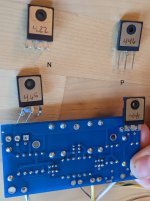
I'm not sure what grade / Idss my JFETs are. My power transistors have some numbers on the back (for matching?) see pics below. I took a shot in the dark and swapped out my N-channel, no difference in behavior.
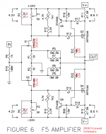
Please note that the resistor labels have changed on the latest schematic / board. I've attached the schematic these boards used.
On first turn on I was only able to bias to about 0.22V across R11 / R12 with zero output offset with P2 at maximum. I swapped the resistors across the trimmers (R3/R4) to 4.75k. That helped a bit, now I can reach about 0.32V across the bias resistors, but again I am out of adjustment on the P2 trimmer.
Is it safe to increase the value of R3 and R4 further? Is there something else funky going on?
I'm testing with a pair of unfiltered SMPS as my power supply for now, they hold steady at 23.9V while I adjust bias.
I'm not sure what grade / Idss my JFETs are. My power transistors have some numbers on the back (for matching?) see pics below. I took a shot in the dark and swapped out my N-channel, no difference in behavior.
Please note that the resistor labels have changed on the latest schematic / board. I've attached the schematic these boards used.
Attachments
Last edited:
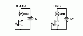
you can measure voltage across 10R JFet source resistors, to know what their Iq is
if everything is behaving, but you're short with mos Iq, feel free to increase JFet drain resistances (R3,R4 according to sch you posted)
if everything is behaving, but you're short with mos Iq, feel free to increase JFet drain resistances (R3,R4 according to sch you posted)
Installed the new Randy T board in my First Watt F5 Turbo V2 today. Very easy to install with Randy's great instructions. No smoke! Sounds great!
https://public.fotki.com/Rbertalotto/hifi-stereo-stuff/pass-labs-first-wat/p1040695.html
https://public.fotki.com/Rbertalotto/hifi-stereo-stuff/pass-labs-first-wat/p1040695.html
you can measure voltage across 10R JFet source resistors, to know what their Iq is
if everything is behaving, but you're short with mos Iq, feel free to increase JFet drain resistances (R3,R4 according to sch you posted)
I just started to measure, saw 46mV on R1 and 24mV on R2, implies N-JFET Iq is 4.6mA and P-JFET Iq is 2.4mA. Thought to myself, hmm those should be more equal, then watched as N-mos bias went to zero, offset voltage went to 7V. Got scared and turned it off.
I turned both trimmers back down to zero. Powered back up. Now I measure 288mV on R1 and 27mV on R2. No smoke came out, but I'm guessing the N JFET is
 , maybe the P too?
repeat JFet (source resistors voltages) measurements where you have set so-so output DC offset near 0V
where you got your JFets?
where you got your JFets?
Tried biasing from the start again. N side bias resistor doesn't go up, P side up to around 100mV and I see DC offset around 7V. Too scared to crank it further since I'm not seeing any N bias.
Got the JFETs from tech-diy like 10 years ago, back when they supplied parts kits.
Got the JFETs from tech-diy like 10 years ago, back when they supplied parts kits.
What's a Randy T board, and where did you get the lighted power switch?Installed the new Randy T board in my First Watt F5 Turbo V2 today. Very easy to install with Randy's great instructions. No smoke! Sounds great!
https://public.fotki.com/Rbertalotto/hifi-stereo-stuff/pass-labs-first-wat/p1040695.html
Randy is here on this board in the PASS LABS area....The 120V lighted switch was from AMAZON:
https://www.amazon.com/gp/product/B07G4BQF5C/ref=ppx_yo_dt_b_asin_title_o08_s00?ie=UTF8&psc=1
https://www.amazon.com/gp/product/B07G4BQF5C/ref=ppx_yo_dt_b_asin_title_o08_s00?ie=UTF8&psc=1
I want to build the v3 of this amp, but the DIYAudio marketplace seems to be out of the match JFETs - the hard to come by Toshibas. I was hoping I could get insight into whether they will be able to restock these or whether there was another source. I am ready to pull the trigger on the boards, PS, Deluxe 4U case, etc. Just missing these parts to have my BOM ready to go.
They are available from seller punkydawgs on eBay.I want to build the v3 of this amp, but the DIYAudio marketplace seems to be out of the match JFETs - the hard to come by Toshibas. I was hoping I could get insight into whether they will be able to restock these or whether there was another source. I am ready to pull the trigger on the boards, PS, Deluxe 4U case, etc. Just missing these parts to have my BOM ready to go.
Thank you!They are available from seller punkydawgs on eBay.
mamsterla,
The store has the 6mA to 8mA Idss jfets available: https://diyaudiostore.com/collections/frontpage/products/matched-jfets?variant=39335247020105
Those will be fine for an F5.
Edit: Also, may I suggest you use a higher power resistor (say 2W) for the 10 ohm source resistors for the jfets (R3 and R4) in the schematics on page 2 here: https://firstwatt.com/pdf/art_f5_turbo.pdf . The reason is that as the voltage level approaches clipping (near +/-20-ish volts), the peak dissipations at R3 and R4 are over one watt.
Last edited:
your F5 with P3 centred certainly looks different to mine, you've around 23dB difference between H2 & 3.. you've quite a bit of noise in your plot tooHas anybody tried to tweak F5 with P3 so its spectrum of distortion at 1 W is like this of F7
with 10 dB between 2nd and 3rd harmonic?
The distortion harmonics of my F5 with P3 at the middle position look like this:View attachment 1010171View attachment 1010172
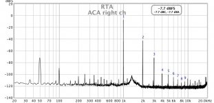
here's my F5 with P3 centred by turns and also 2 turns from centre
for interest I also attached my ACA plot
think I'll centre P3 by resistance next time I've the amp lid off and see what I get
Attachments
Last edited:
- Home
- Amplifiers
- Pass Labs
- F5 power amplifier