Hi all,
Firstly, I would like to thank everyone that helped me with my F5 (& DCB1): 6L6 for those invaluable build guides for newbies like me, Salas and Andrew with my DCB1, and countless others on the diyaudio site and Mr Pass for making it all possible. When I finally played some music on my F5 it was one of those rare audio moments when I could really hear a difference from my current Exposure 2010S2 integrated, which is no slouch BTW. The F5 sounded wonderful—so clear and natural—even through my $5 test speakers. I was giggling all by myself.
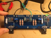
Alas, there’s just one niggling problem; the dreaded hum or in my case a what I would call a “hum-buzz” coming from the transformer, Antek AS-4218 (400VA 18V), which is also audible in the speakers as an almost imperceptible 120hz hum with a slightly buzzy edge. I didn’t notice it right away since I tested the channels separately. However, when everything checked out and I connected both channels, the noise happened. If I disconnect one channel, it goes away or is reduced to the point that I can barely hear it even though the transfo keeps buzzing. I eliminated the DCB1 as the problem by connecting one IC between the amps inputs: hum-buzz when connected, gone with either one disconnected. I assumed a ground loop. So after trying several things, rerouting and shortening wires, checking all the returns and grounds, different outlets and even Joffe’s HBRR & HBRL(thanks Andrew) to no avail I decided to move the transfo outside of the chassis. First thing I noticed is the transfo doesn’t buzz unloaded. Measured 19Vac on each secondaries unloaded and + and - 25Vdc on PSU(diyaudio PSU PCB v3 with two bridge rectifiers, Epcos 15000uf 50v x 8 caps). Once under load, transfo starts to buzz but no buzz through the speakers. Back in the chassis, transfo and speakers buzzing. Measured AC on speaker outputs and got between 4 and -2mVac at first but then settled right around 1 to 0mVac. I’m attaching a picture and drawing of how the returns and grounds are wired as well as chassis overview.
So, I guess my question is if I should put it down to a faulty transformer and contact Antek—there is one copper wire that seems to bulge out a bit more than the others— before going even further chasing the hum-buzz. Any advice would be greatly appreciated.
Thanks
I am not sure but I accidentally discovered CL-60's conduct on their shells...I did get a shock too, in my circuits I cover them up using a large heat shrink tube...from the pic, the ground CL-60 and the PS CL-60's are quite close to the bottom chassis....suspect if they are touching in any form may add to distortion when current draw is more...
Sent from my iPhone using Tapatalk Pro
I don't think you should be adding any thermal insulation around your Power NTCs............CL-60's .........I cover them up using a large heat shrink tube............
They run hot if they pass big currents.
That's why I keep saying they should be bypassed.
But like all mains connected components they do need to be separated from touching any earthed finger, or chassis, or amplifier.
I don't think you should be adding any thermal insulation around your Power NTCs.
They run hot if they pass big currents.
That's why I keep saying they should be bypassed.
But like all mains connected components they do need to be separated from touching any earthed finger, or chassis, or amplifier.
Makes sense...understood
Sent from my iPhone using Tapatalk Pro
Something like this. Solid State Power Amplifier Supply Part 2
i think this is the same as the power supply pcb's from the diyaudio store. I have one in my F5 feeding both channels. i was planning to add another one and another toroid transformer. this way i think i will have pure monoblocks. am i wrong?
is this that simple? or any other changes?
Hey guys quick question, can I use 27V Transformers for the F5 or is the voltage rating too high ? Is a Heatsink with 0,7K/W sufficient ? Do I need to replace the capacitors with ones with higher voltage ratings ?
Values : http://www.diy-audio-shop.de/wp-content/uploads/2016/12/BJT-F5_Values.png
Schematic : http://www.diy-audio-shop.de/wp-content/uploads/2016/12/BJT-F5_Schematic.png
Values : http://www.diy-audio-shop.de/wp-content/uploads/2016/12/BJT-F5_Values.png
Schematic : http://www.diy-audio-shop.de/wp-content/uploads/2016/12/BJT-F5_Schematic.png
Last edited:
if 2x27Vac , you can , cascoding input JFets
0.7K/W is not enough even for one channel
read F5Turbo article
0.7K/W is not enough even for one channel
read F5Turbo article
Bias adjustment
After having some bad luck with Ebay jfets I received my new Linear systems parts from DIY audio and have now installed. I have set P1 and P2 to there lowest value (adjusted fully counter-clockwise) I am not seeing any voltage change when measuring across R7/R8....even with maximum adjustment on P1/P2.
I am happy there was no smoke this time but am really at a loss of where to go from here.......
hi
im going to make monoblocks. i have one 400va toroid in my F5. would you buy 2 of 200va or add another one with 400va? never built monoblocks and i am trying to find a reasonable way to do it. dont want to go crazy.
thank you
im going to make monoblocks. i have one 400va toroid in my F5. would you buy 2 of 200va or add another one with 400va? never built monoblocks and i am trying to find a reasonable way to do it. dont want to go crazy.
thank you
Yep, it's monoblocks. Will be expensive no matter what because of 2 chassis. Get matching transformers. Another 400 or two 200, whichever.
😀 😀 😀
😀 😀 😀
that's what i thought! 😀
the second chassis will be made of the existing one. the idea is to buy the spare parts from hifi2000 (bottom, top and side plate). the front panel is in the making. only the heatsinks will remain.
the second chassis will be made of the existing one. the idea is to buy the spare parts from hifi2000 (bottom, top and side plate). the front panel is in the making. only the heatsinks will remain.
what Idss values are these JFets ?
I ordered Grade "A" which are listed as 2.6-6.5
Oh.
Make the resistor in series with the pots 4.7k or so. Increase that resistance until you can get bias.
Make the resistor in series with the pots 4.7k or so. Increase that resistance until you can get bias.
I ordered Grade "A" which are listed as 2.6-6.5
Oh.
Make the resistor in series with the pots 4.7k or so. Increase that resistance until you can get bias.
I did put another 2.2k resisitor in series and noted no significant change. I will keep bumping up resistance and see what happens...
Are you getting anything at all? If not, suspect a bad connection somewhere.
Please post some well-lit, in-focus photos.
Please post some well-lit, in-focus photos.
I hope this pic is helpful. One thing odd I am finding is the power supply. Measuring voltage at supply with board unplugged, I am read +/- 25v which seems right, however when powering up board I read +25v and -35v which seems odd to me.
Time to walk away for a bit!
Time to walk away for a bit!
Attachments
Measuring voltage at supply with board unplugged, I am read +/- 25v which seems right,
however when powering up board I read +25v and -35v which seems odd to me.
There's something wrong, be careful. Try two load resistors instead of the pcb.
- Home
- Amplifiers
- Pass Labs
- F5 power amplifier