I read the resistance should be beyond 300 ohm.You cannot test FETs that way.
Can I use the schematic in fig 5 http://www.linearsystems.com/assets... The New Frontier Part 1, by Erno Bordely.pdf
Do you have any suggestion for the diodes. I think 1M resistor should be ok also with 9v battery. Right?
You need dual polarity supply, for the Vp voltage (using the 1M0 resistor)
The Id (2mA and 5mA) vs Vgs also need dual polarity supply.
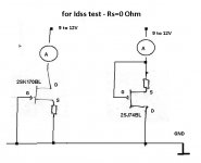
Idss can use single polarity supply.
The Id (2mA and 5mA) vs Vgs also need dual polarity supply.
Idss can use single polarity supply.
yup
Fig. 5
but if you take a look at sch , you'll see that you don't need any resistor - tie S and G , while D is solo
(Idss test is all what you need , at Borbely's sch switch needed for that )
Fig. 5
but if you take a look at sch , you'll see that you don't need any resistor - tie S and G , while D is solo
(Idss test is all what you need , at Borbely's sch switch needed for that )
yes, he asked ;
but we know that he isn't experienced enough to know what's actually needed
more confusion isn't of any benefit
but we know that he isn't experienced enough to know what's actually needed
more confusion isn't of any benefit
here we go again
look (don't use Rs , just ignore it , as 0 Ohm) ;
instead of 12V , you can use 9V battery :
look (don't use Rs , just ignore it , as 0 Ohm) ;
instead of 12V , you can use 9V battery :
Attachments
Last edited:
hello
I need som expertice advice ....
Have built a F5Turbo with choke input spu, that´s given me quite a few headaches
it is built as vertical cylindrical mono towers with powertransfomer in the bottom base and a huge vertical heatsink with F5T and cap.bank pcb are mounted
now to the problem
at startup, amp 1 ramps up to 35vdc and about 270mA bias, and then reaches target 350mVand 31,5vdc in about 30mins
amp 2 ramps up to above 38vdc and about 200mA and then uses a good hour to reach target of 350mA
once at target they both get about 31,5vdc from psu and main heatsink temp is about 50C
the powertransformers are 1KVA dual 50VAC into full wave MUR860, Hammond 60mH2A chokes followed by series ARCOL HS1508R on dedicated heatsink and then dual parallelled 400R Caddock bleeders.......
suspect some thing has gone south when startup voltages exceeded 40dc on amp 2, before I got the bleeder in
however both sounds normal
all replies welcome
best
Leif
Does the bias and offset stabilize when up to operating temperature?
If yes, then everything is probably fine - these amps are always moving until the heatsinks are hot.
If yes, then everything is probably fine - these amps are always moving until the heatsinks are hot.
yes they do, but I don´t see why one is getting to target bias so much faster than the other
and I´ve struggled for weeks with the overshooting voltage at startup with the slow one
was seriously worried for the driver transistors that got above 40v several times
best
Leif
and I´ve struggled for weeks with the overshooting voltage at startup with the slow one
was seriously worried for the driver transistors that got above 40v several times
best
Leif
I´ve struggled for weeks with the overshooting voltage at startup
That is a function of choke input PSU. Replace with resistor and the PSU overshoot will go away.
as will the harmonics 🙄That is a function of choke input PSU. Replace with resistor and the PSU overshoot will go away.
best
Leif
thought so, but maybe not exactlydrain thermistors mounted in same way on both channels ?
good point..will check
thxs
best
Leif
Have you measured the actual resistance of each resistor? If there is a difference it will explain your measurements.
The good news is you can achieve that bias with zero DC offset.
With my cheap meter I measured R11 and R12
R12 0.6 ohm
R11 0.9 ohm
resistors are marked 0.47 ohm 5%!?
I replaced R11
What does your meter read when the two probes are placed on the lead out wire on ONE side of the resistor?
That reading should be subtracted from the reading you get across the resistor.
For low value resistors, this "correction" makes a big difference.
Simply placing probe to probe misses out a connection. It may read the same as probes on the lead out, it may not. It depends on the resolution of the DMM and the consistency/repeatability of the instrument.
Learn to use your instruments and in particular learn what they are not good at.
Learn how to "compare" REF to DUT. It becomes the most powerful tool you can posses.
We amateurs with limited resources are not good at "absolute" measuring.
eg. I can't measure a resistor to any better then 1%. But I can compare resistors using a variety of methods and get matching to better than 0.02%
Last edited:
and then dual parallelled 400R Caddock bleeders......
200R is too small for bleeder....
- Home
- Amplifiers
- Pass Labs
- F5 power amplifier