disassemble/reassemble is most logical. One step at a time - one channel at a time. Sounds like a lot of extra work, but often we have to go that far back to reveal the problem..
You're right.
It's the case I open a new thread?
At this point I have the f5 boards disconnected. I have 48v, what I have to check before going to next step?
OK, take your time and re-read that build PDF fully before you start putting the amp back together. If you have questions or don't understand something - pleas ask before you even heat up the soldering iron. : 😉
Last edited:
Reminder
Audio gear does not need a Safety earth to operate.
Audio Gear NEEDs a common grounding system that can be at any isolated voltage. Battery powered gear works like that. It works well.
The Protective Earth (or Safety Earth) is ONLY required for SAFETY. It has nothing to do with audio.
Our washing machines, tumble driers, vacuum cleaners, televisions, audio, etc would all work perfectly well without a Protective Earth.
But many more of us would be injured, or worse, if non protected mains powered electrical were generally on sale.
We have two main electrical standards for domestic equipment.
Class1 have a Protective Earth.
Class11 are double insulated.
These two standards are what keeps us alive to use and enjoy the benefits our mains powered equipment.
Greetings!
It's been a few months since I've started reading up on the whole DIY thing. I want to build this F5 point-to-point and am wondering if there is anything I should consider when placing the parts.
I've had a fun afternoon with ms paint and came up with a design.
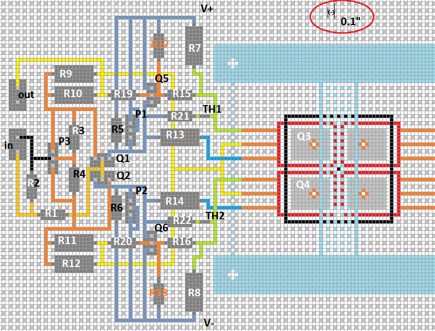
Not really thought about anything special except the transistor placement. I want them to be as close as possible, because I will not be using the bulky heat sinks.
I'd be happy if someone would be so kind to look over my ms paint design and tell me if there's anything wrong and where to put out-.
Q1 is left-to-right S-G-D, Q2 is D-G-S, Q3/Q4 is top-to-bottom S-G-D and Q5 is E-B-C, Q6 is C-B-E if it isn't clear in the picture. I've tried to show the flat sides of the jfet/bpt and the metal on the mosfets. Not sure if one can tell with all the wires going there and the picture being ms paint.
🙂
point to point does not have to be laid out in 2D format.
You can use 3D if it helps with locating components near where they belong.
Here's an example:
http://www.diyaudio.com/forums/blogs/wintermute/134-construction-p2p-lm3886-gainclone-part-1.html
or
you can go back to valve/tube style layout using "tag strip" to support devices and components
You can use 3D if it helps with locating components near where they belong.
Here's an example:
http://www.diyaudio.com/forums/blogs/wintermute/134-construction-p2p-lm3886-gainclone-part-1.html
or
you can go back to valve/tube style layout using "tag strip" to support devices and components
I want them to be as close as possible, because I will not be using the bulky heat sinks.
If you are not using bulky heatsinks how will you be managing the (large amounts of) waste heat?
point to point does not have to be laid out in 2D format.
You can use 3D if it helps with locating components near where they belong.
Here's an example:
http://www.diyaudio.com/forums/blogs/wintermute/134-construction-p2p-lm3886-gainclone-part-1.html
or
you can go back to valve/tube style layout using "tag strip" to support devices and components
Woops. I didn't know what point-to-point meant. Sorry. What I wanted to say is I won't be using a printed board, because i can't afford a custom one. Will be using wires to connect the parts. I thought this was where point to point came from, as I would be connecting point to point with wires... I don't know 🙂
If you are not using bulky heatsinks how will you be managing the (large amounts of) waste heat?
I was thinking of using either a 1155 cpu socket cooler (the brackets are already in the picture, 75mm x 75mm) and if that is not sufficient I will be using a waterblock in the same dimensions.
I didn't do any calculations, but I've based this on the TDP of modern overclocked CPUs (~150W+) which are easily cooled by either of those - and they're doing it down to <80°C. This would make the build cheaper and smaller.
ClassA is never built "cheaper".
It demands money !
P2P does use wires to connect between the points.
Your understanding was and is correct.
But it does not have to be 2D. It can be linear, or 2D, or 3D. Or a bit of all three.
It demands money !
P2P does use wires to connect between the points.
Your understanding was and is correct.
But it does not have to be 2D. It can be linear, or 2D, or 3D. Or a bit of all three.
I didn't do any calculations, but I've based this on the TDP of modern overclocked CPUs (~150W+) which are easily cooled by either of those - and they're doing it down to <80°C. This would make the build cheaper and smaller.
That's really not enough heatsink. All 4 transistors together will be running at a constant 115W, and they need to be cooled to 65C, which is an approx heatsink fin temp of 55C. One cooler will require the fan at max RPM, and should the fan fail, so will the amp.
Still, I like the idea, and water might be a good answer, or perhaps both, depending on what you have on hand. The amp sounds wonderful, you'll love it , and the project is completely worth pursuing. 🙂
[...], and should the fan fail, so will the amp.
That's what I'm worried about. I know I shouldn't be taking chances with this, but I've had 5+ fans running in my desktop for many years and not even once did one fail. They sometimes start making noises and that's when I replace them. A pump could fail, too. Mine didn't fail in the 7 years since I've installed it on my desktop, though. My desktop is running 24/7.
I'm not sure about the rpm - part. Modern CPU coolers claim they can dissipate that amount of heat with a silent 120-140mm fan running at less than 1200rpm.
We will see!
I'm in the process of finishing up my order on mouser and am looking for sources of jfets in the EU. Thanks again for your encouragement - this time I am determined to see it through. It's been long enough since I've first started thinking about it 🙂
Try overclocking your CPU as high it will go, raise the volts to the max, and that is when you are able to hit the printed TDP ceiling or exceed it a bit. CPU coolers do not have to deal with extended periods of maximum dissipation, there is always time when the system is idling. No such luck, with an amp like this.
Water, maybe. I have a system that pushes about 350w of heat, with two hot video cards and an equally power hungry CPU. Using about 4 120mm fans worth of radiator, and that is just about adequate to keep everything down in the late 50s, though in peak summer i've seen low ro mid 60s on some components. Water temp is usually about 45. Your next problem will be to mount the block to the transistors. It's been done right here, on the F5 turbo thread but required a custom block. Air cooling will be very difficult and probably not wise.
Water, maybe. I have a system that pushes about 350w of heat, with two hot video cards and an equally power hungry CPU. Using about 4 120mm fans worth of radiator, and that is just about adequate to keep everything down in the late 50s, though in peak summer i've seen low ro mid 60s on some components. Water temp is usually about 45. Your next problem will be to mount the block to the transistors. It's been done right here, on the F5 turbo thread but required a custom block. Air cooling will be very difficult and probably not wise.
A short commercial from the local Water Department 🙄
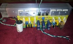
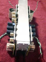
Development on a multi-use liquid cooling chassis is progressing. It has a new horizontal format as opposed to the earlier F5 & BA-3 LC builds. A larger unit for longer boards will be a separate item.
I'm mentioning it here for a reference to heat management for an F5. The photos show a prototype that can maintain 12 output devices at 85% of full class A operation - with only an 6" (120mm) fan. Pump noise is no longer a problem, and I'm currently determining the optimum fan configuration for noise and air flow. At present it appears something as small as a standard 80mm fan will do the job for an F5. Worse case is a distance of 3 - 4 feet to not hear a modern fan. Better results can be achieved and some alternate units have been ordered. A single 120mm fan at 40 - 60% max speed is quiet at 1 foot but requires a larger chassis.
"One cooler will require the fan at max RPM, and should the fan fail, so will the amp."
The BA-3 amp has a temperature sensor that stops the main AC at 68 degrees on the outputs. Other temps can be chosen if desired.
I encourage others to jump on the 'water wagon' as new developments in the PC cooling community make the concept much more adaptable to power amps.
Stay tuned........😉
Attachments
Last edited:
Audio gear does not need a Safety earth to operate.
Should be the topic of another thread. Some of these safety issues differ between the US/Canada and Europe.
The highly safety conscious, belt and suspenders American Radio Relay League recommends a safety ground, and not switching the neutral -- there's a good chunk of a chapter in the ARRL handbook dealing with "earthing".
The highly safety conscious, belt and suspenders American Radio Relay League recommends a safety ground, and not switching the neutral --
A fine guideline. Hopefully people will wire their amps that way.
The opposite, caution to the wind approach was in a project for a Stax Headphone amp I saw over at Head-Fi, where the 600V was made from a Cockcroft-Walton voltage multiplier directly off the AC mains. 😱😱😱
The only nod to safety was somebody imploring the Mods to lock the thread due to that, (rectifying the mains, not to mention making 600V from it with not even an isolation transformer) and somebody else mentioning how that discussion would be banned here at diyAudio. Of course nobody paid heed...
ProbablyShould be the topic of another thread. Some of these safety issues differ between the US/Canada and Europe.
The highly safety conscious, belt and suspenders American Radio Relay League recommends a safety ground, and not switching the neutral -- there's a good chunk of a chapter in the ARRL handbook dealing with "earthing".
We need to protect ourselves and our families/friends from mistakes in our chosen hobby.
The Forum already bans all discussion on direct to mains equipment, except when.....
It does not yet ban discussion on Class11, nor Class111 equipment building.
The Forum seems to condone the building of Class1 equipment but the "Rules" are not explicit.
Class1 equipment MUST have a protected Chassis.
Class1 exposed conductive parts MUST be connected to that protected Chassis
Neither of these two demands has anything to do with AUDIO.
The Audio parts will work perfectly well without any Chassis, whether protected or not.
The "demands" are exclusively for SAFETY.
Last edited:
I was directed to using thermostats for temperature protection. There's the simple close-on-rise ones which would be directly fed by mains voltage. However, I don't want the mains leads to go all the way to the heatsink, and these simple ones don't have a hysteresis so in case of overtemperature the amp would turn on and off pretty often.
I then came across these ICs from TI, the LM26. I could have these control a relais which would switch the mains. I would split the mains so the control circuit wouldn't switch itself, otherwise the amp would never switch on.
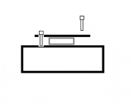
Since the LM26 is in a very small SOT23 - package I am wondering if I have to take any special care about wire lengths or other things. I was thinking of using the recommended application for a thermostat ( figure 7 in the datasheet http://www.ti.com/lit/ds/symlink/lm26.pdf ), having the wires go from the IC to another small board which would have the rest of the circuit. To avoid shorts I'd use a sot->dip adapter board, solder sockets for a fan connection on them and use fan cables to connect.
Good/bad? What would i actually use to "glue" the LM26 on the heatsink?
I then came across these ICs from TI, the LM26. I could have these control a relais which would switch the mains. I would split the mains so the control circuit wouldn't switch itself, otherwise the amp would never switch on.
Since the LM26 is in a very small SOT23 - package I am wondering if I have to take any special care about wire lengths or other things. I was thinking of using the recommended application for a thermostat ( figure 7 in the datasheet http://www.ti.com/lit/ds/symlink/lm26.pdf ), having the wires go from the IC to another small board which would have the rest of the circuit. To avoid shorts I'd use a sot->dip adapter board, solder sockets for a fan connection on them and use fan cables to connect.
Good/bad? What would i actually use to "glue" the LM26 on the heatsink?
Arctic Silver Thermal Adhesive
But you don't have to glue it. Any bracket/keeper with a screw or two will hold the chip tight and allow for replacement/modification.
But you don't have to glue it. Any bracket/keeper with a screw or two will hold the chip tight and allow for replacement/modification.
Attachments
Last edited:
- Home
- Amplifiers
- Pass Labs
- F5 power amplifier