I'm still puzzled as to what you did wrong in the first place ?
Did you connect the 110V primaries in parallel instead of in series ?
Even worse inverse parallel ?
Luckily transformers are pretty resilient when used with the correct fuse.
The guide tells to mark the primaries to recognize the pairs. I made a mistake.
The transformer should have been marked with the start and finish of each winding. We all make mistakes, luckily you have found out what was wrong and nothing was burned.
I'm having a bit of a problem with my F5 - it may be a problem with the Impasse pre-amp.
I've got a bit of sibilance. definite Tsssss when a voice says S.
I've got a bit of sibilance. definite Tsssss when a voice says S.
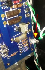
update: now I have an output voltage from psu cap board of 23.5v. But when I connected the f5 boards the bulb lights on. So I checked the boards and Q5 and Q6 were placed in inverse position (cbe-ebc). I've repositioned them but still it doesn't work. Any suggestion?
It's normal for the bulb to stay on when the complete amp is connected. Follow the instructions near the end of this post.
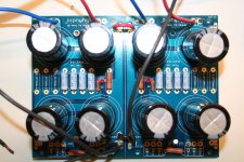
An illustrated guide to building an F5
An illustrated guide to building an F5
It's normal for the bulb to stay on when the complete amp is connected. Follow the instructions near the end of this post.
An illustrated guide to building an F5
But the control leds in the f5 boards remain off

Those look good to me, but I'm a fellow builder not an expert. Have you been able to follow along with the adjustments in the pictorial linked to a few posts back? Pictures of your full configuration are also very helpful for trouble shooting. It appears you have already purchased a chassis for your build. How are you placing the components?
Last edited:
Tube in the pre?
If that was an answer to my question, I have tried alternative tubes and it makes no difference.
bcmbob;3753553Have you been able to follow along with the adjustments in the pictorial linked to a few posts back? How are you placing the components?[/QUOTE said:I didn't tried to turn on the boards because when I tried the leds didn't light on and the fuse blown. The enclosure is from hifi2000, I placed the f5 boards laterally on the heatsinks, the trafo in the center, the caps on the front panel.
Are you sure the polarity of the LEDs is correct.
no, now I desolder them and check them with a battery.
You don't need to desolder them.
Arrange a low voltage supply (6V or 9V battery) and a current limiting resistor.
Apply probes to each LED in turn.
Arrange a low voltage supply (6V or 9V battery) and a current limiting resistor.
Apply probes to each LED in turn.
I'm trying with a 1.2v battery but nothing. In the sheet I see the led requires max 2v, but I can't light on neither the one of the psu nor those of the boards.
Last edited:
1.2V is not enough to illuminate the LED. You need a touch more, try 1.8V, preferably a bit more with a series resistor.
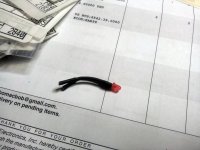
For convenience and possible remote placement on front panel - LED, Small copper tube and heat shrink.
Are you still blowing fuses, and/or can you get a voltage reading from the LED pads?
Are you still blowing fuses, and/or can you get a voltage reading from the LED pads?
Attachments
Last edited:
- Home
- Amplifiers
- Pass Labs
- F5 power amplifier