my welder had a problem so I made some troubleshooting and I found that it had no grounding and the heat point had 40v ac. Now I solved the welder warms again I grounded the point. Can that 50v ac damaged the transistors?
nope , unless you're soldering them while circ is ON
I hope you're not doing that ......... from several reasons

I hope you're not doing that ......... from several reasons
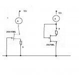
can you give me a scheme?pull out all semis and test them with simple matching jig
my led is not working can this give me an open?
http://www.firstwatt.com/pdf/art_mos_test.pdf
small bjts you can test with diode test on your DMM ; http://www.bcae1.com/
you can use 10R for in lower pic
use 9V battery for V
small bjts you can test with diode test on your DMM ; http://www.bcae1.com/
you can use 10R for in lower pic
use 9V battery for V
Attachments
Last edited:
thank you zen. Perfect I've broken a pin of ztx550. So now I'm sure it's fault. Do I have to check all the transistors Q1-Q6? What about the led fact?
dunno - broken pin of ZTX can be or not
regarding led - is it oriented as needed ?
who cares for LED , if you have proper PSU voltages on pcb ?
check all semis , replace what's needed , try again - following any of published start-up tutorials
regarding led - is it oriented as needed ?
who cares for LED , if you have proper PSU voltages on pcb ?
check all semis , replace what's needed , try again - following any of published start-up tutorials
I've checked ztx450 and the hfe is circa 300 but it increases to 1000. I think it should be 100-300. Is it normal?
Going back to biassing, the bias current wil not start to rise until the output FETs start to turn ON.
Once you have replaced the semis just trrying turning up the bias two turns at a time until the output FETs start to conduct. Then you can adjust the bias as necessary.
Once you have replaced the semis just trrying turning up the bias two turns at a time until the output FETs start to conduct. Then you can adjust the bias as necessary.
I've checked ztx450 and the hfe is circa 300 but it increases to 1000. I think it should be 100-300. Is it normal?
ztx are "just" current limiters , in case something goes south
besides that - it's either bad battery in your DMM or shitty DMM
that reading is , well , wrong
open new thread with plenty of pictures
I can't follow here what you made , what you checked and what not
I can't follow here what you made , what you checked and what not
Glad to say that my repair is looking good. The F5 really didn't like being biased at 3A (ish).
... The F5 really didn't like being biased at 3A (ish).
Obviously. I bet any other amp can take 3A per MOSFET with ease... 🙄
Babelfish J , 2A per IRFP150N vertical , 22Vdc rails
hey , but that's only because I'm ignorant

hey , but that's only because I'm ignorant
You win.
The Lang amp lost anyway, the original design uses 2 in parallel, makes it 1A per MOSFET.
(in the early '80s, me lots of cheapo heatsink, but only cash for 1 Hitachi pair per channel)
The Lang amp lost anyway, the original design uses 2 in parallel, makes it 1A per MOSFET.
(in the early '80s, me lots of cheapo heatsink, but only cash for 1 Hitachi pair per channel)
- Home
- Amplifiers
- Pass Labs
- F5 power amplifier