No, I don't have any fuses in the DC path/s. Only a 2A fuse in the 240VAC line.David,
have you fused the main power rails between amp and smoothing?
Regards, David.
Seems like my "very hot" is equal to Papas "Bloody Hot". I will have to test some forced cooling options as we have a youg kid in the house.
My comment was more to the issue of how I am amazed that these 2 small devices can create so much heat and still keep the smoke in.
Thanks for the pointers - maybe when I am done I can post the reults ( convection and forced cooling) to help any future new constructors , as I have noticed that heat sinking is a common cause of questions.
And for the F5 turbo seems like we are going to need some serious heat sinks for that one.
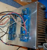
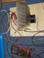
OK, I have tried some experiments with forced cooling - with a fan attached I can run one F5 channel on the heat sink at 34 degres C or both F5 modules on the same heat sink, the heat sink is 42 degrees C (with convection it was 54 degrees C with only one channel)
The fan I am using is a 24 volt unit with a 35CFM rating (with a 41dBA noise rating - very nosiey, but all I had at hand to test) - I am running it at 19V from an old switch mode laptop power supply (yes they do have uses) (I am having trouble downloading the derating table for reduced voltage - so cant really say what the CFM is at present , but it is less than 35 CFM)
I have the amp setup as per instructons, the supply voltage is +/- 23.5 Volts, for R11 and R12 the voltage is between 0.59 and .6, giving an offset voltage at the output at less than 2mV
Also I have used a fully encapsulated transformer (Noratel brand), it is rated at 225Va (I will 1 per channel) but at present I am running both channels off one transformer just to check for hum under heavy current load (and it is easier for testing, less wires every where), there is absolutely no hum - these appear to be a great solution for heavy current draw applications - under these conditions it is quite warm, about 43 degrees C
Other adventures - maybe this will help othes who make dumb mistakes like me - ie connect the power supply round the wrong way ( moral to the story is dont rush to test the amp , take your time and check and check again)- lots of glowing resistors ( R11 and 12 anyway) toasted Q3, Q4, Q1 and Q2. What really suprised me is that it also cooked P1 and P2 - check these as if you power up again with these cooked - what I mean is the wiper point was open circuit ad so I got the 5K which gives a high bias current and so R11 and R12 start to glow again and let out smoke.
Attachments
Last edited:
Only difference in builds is that this time I used some self adhesive heat sink washers. Grey looking like normal washers but very soft and squishy. Anyone had trouble with these? I'm now using the normal grey washers and amps are OK (so far!).
What did you use the first time?
😎
Nelson
The previous two F5 builds have used the standard grey flexible heat transfer washers. They look like they may be some sort of fabric covered in grey (silicon?) material. I have used them on other projects and never had a problem.
One other change is that I did a triple plait with the pos/neg/earth DC leads between the PS rails and the F5 PCB. I seem to remember now that this might not be the best way of running these wires.
Thank you for your interest in helping me.
I managed to get my PEH200 from Elfa. You are comparing two capacitors with a whole of different specs, thats why you see big differences between PEH200 and PEH169. You have to compare capacitors with same capacitance and voltage rating, otherwise it is useless.Thanks Regi.
Were you able to find the 47.000 PEH169 anywhere ?
IMHO, I would go with 47.000uF PEH200 better than 22.000uF PEH169
I managed to get my PEH200 from Elfa. You are comparing two capacitors with a whole of different specs, thats why you see big differences between PEH200 and PEH169. You have to compare capacitors with same capacitance and voltage rating, otherwise it is useless.
IMHO, I would go with 47.000uF PEH200 better than 22.000uF PEH169
Thanks a lot for the info Regiregi, I'll follow your suggestion.
I didn't know the Elfa Distrelec dealer, very interesting.
ciao, have a nice day. Carlo.

The 44,000uF of Rifa caps per rail is going to produce a massive turn-on current surge - also, 15,000/40v caps will do quite well in the basic CRC but still need a Soft Start/ CL60 limiter cct -
Not much difference in the sound of the peh200 and peh169 for the same uF value - best with fast, soft recovery diodes and avoid the common block bridges (sound is quite hard, rough with these caps) - the combination of 0.1R, 15,000uF, 0.1R, 15000uF (RCRC) is a fairly well known configuration (extra series resistor after diodes - no ceramic wirewounds)
The threaded stubs on the case is for cooling the capacitor case on a heatsink - can just cut them off, insulate the case and use capacitor clamps - best mounted vertical - Not the easiest cap to use but very fast, "punchie", bright cap, slow to break-in & very long life ...
... my 2 cents
I used a softstart board, but slow blow fuses should do the trick.The 44,000uF of Rifa caps per rail is going to produce a massive turn-on current surge - also, 15,000/40v caps will do quite well in the basic CRC but still need a Soft Start/ CL60 limiter cct -
Thanks jh. An IXYS FRED bridge like this, you mean ?Not much difference in the sound of the peh200 and peh169 for the same uF value - best with fast, soft recovery diodes and avoid the common block bridges (sound is quite hard, rough with these caps)
http://www.partsconnexion.com/product4794.html
Yeah Regi, SoftStart and Slow fuse, just fine - I was quite surprised at the Rifa charge/discharge rates - not written directly in the specs.
IXYS bridges okay - there's some diodes specifically built for the job - fast, soft recovery - ON versions like MSRF1560, can't remember the Phillips equiv - don't be put off by the relatively slow Trr (about 50nS) - those Rifa caps are a bit harder to please than most.
Can balance the sound of the amp a lot with carbon, etc (softer) Fet gate stopper resistors and metal ox in the RCRC (suggest you avoid the common Nichrome ones) without losing the "grunt" and "speed" - most other power supply caps not so critical altho some of the BHCs need some care also to bring out the exc. mids/tops (ie. the DNM versions 4 pole & slit foils)
I did try a balance with Sikorels for the ripple cap and the Rifas as the power cap (ie 0.1R, Siemens 10,000uF, 0.12R, Rifa 15,000uF) with the BYV diodes (on heatsinks) for PHY-HP based speakers & copper spkr wires - rather good result.
Geofd:
Here is another fan cooled solution that works very well for 2 channels.
http://www.diyaudio.com/forums/pass-labs/121228-f5-power-amplifier-1021.html#post2453420
Here is another fan cooled solution that works very well for 2 channels.
http://www.diyaudio.com/forums/pass-labs/121228-f5-power-amplifier-1021.html#post2453420
In what sense?Yeah Regi, SoftStart and Slow fuse, just fine -- not written directly in the specs.Code:I was quite surprised at the Rifa charge/discharge rates
I finished up my f5 last night and have been enjoying listening to it this morning.....sounds great. I have a couple of questions, excuse me if they were answered somewhere else and I missed it.
My voltage is a little low, about 22 volts. Should I set the bias higher then the specified .6 volts?
I used an atek transformer with a shield between the primary and secondary. I assume that the shield is grounded with the safety ground. Is this correct?
My voltage is a little low, about 22 volts. Should I set the bias higher then the specified .6 volts?
I used an atek transformer with a shield between the primary and secondary. I assume that the shield is grounded with the safety ground. Is this correct?
Evan, the amp likes nice (as seen on other thread)
Under load, that voltage is right.
I would bias higher only heat on sinks and in case is reasonable.
PS - I beleive the shield wire is correct, but have no authority on that matter.
Under load, that voltage is right.
I would bias higher only heat on sinks and in case is reasonable.
PS - I beleive the shield wire is correct, but have no authority on that matter.
Thanks Mike. It's folks like you that are setting novices like me up for success. The amp has been on all morning and is nice and warm. I have no way to check the temp of the mosfets, but I can touch them and they are only warm. The thing that surprised me is how hot the rectifiers are. Maybe a little more aluminum for them.
Evan
Evan
Should I set the bias higher then the specified .6 volts?
This does surprise me...........check the temp of the mosfets, but I can touch them and they are only warm. The thing that surprised me is how hot the rectifiers are.
The diode bridge only has 1.2V across it whereas the mosFETs have 22V across them. Both are passing similar currents, so I would expect the mosFETs to be more than "only warm".
How did you measure the 0.6 volt?
Geofd:
Here is another fan cooled solution that works very well for 2 channels.
http://www.diyaudio.com/forums/pass-labs/121228-f5-power-amplifier-1021.html#post2453420
Great solution, and yes the fans are really good option to keep heat sink size down and so keep costs down
I have used to 80mm fans from a company called noise blocker - at rated 12V they make only 6 dBa of noise (extremely quiet, running at 1200rpm at 12v) - some asked after your post about PWN etc - these fans run at rated voltage so no issue or use of PWM, no switching noise or vibration. so I can run them in series of the same supply as the amp
For me I have the 2 channels running at a stable 43 degrees - seems OK to me temperature wise, and quite compact - oveall dimension of the heat sink amp modules and fans are 280mm x 220mm x 110mm
The last step will be to put a temperaure switch on the heat sink that activates at say 50 degrees C so if a fan fails the cuircuit can cut the power and shut down before it blows up - I did think of using the tacho output from the fan (most PC fans seem to have tacho outputs these days) but this just adds complexity and the possibility of introducing souces of noise as I would need some type of active circuit to monitor the output
I finished up my f5 last night and have been enjoying listening to it this morning.....sounds great. I have a couple of questions, excuse me if they were answered somewhere else and I missed it.
My voltage is a little low, about 22 volts. Should I set the bias higher then the specified .6 volts?
I used an atek transformer with a shield between the primary and secondary. I assume that the shield is grounded with the safety ground. Is this correct?
Hi Evan,
The antek transformers (AS series) only have an outer shield; no shield between primary and secondary windings (I asked John about this directly). The shield ground (purple wire) goes to safety ground, like you assumed.
Andrew .6 volts across the .47ohm resistors passing current to the mosfets. Looks like 1.27 amps. I don't understand the 1.2 volts across the diode bridge. I mosfets have a lot more heatsink then the diode bridges. I may have to add some more metal to there.
Alazira. The antic website claims a static shield between the primary and secondary. Either way it seems to be working well......
Alazira. The antic website claims a static shield between the primary and secondary. Either way it seems to be working well......
- Home
- Amplifiers
- Pass Labs
- F5 power amplifier