antek
From an email dated 10/26/11:
Hello Garrett
Sorry, I made a mistake. They both don't have electrostatics shield in between primary and secondary. AS model has the outer shield and there is a ground wire connects to the outer shield.
Best regards,
Jin
Ango Technology Corp.
25 Ewing Avenue
North Arlington, NJ 07031
Phone# 201-991-3300 Mon - Fri, 9AM-5PM EST
Alazira. The antic website claims a static shield between the primary and secondary. Either way it seems to be working well......
From an email dated 10/26/11:
Hello Garrett
Sorry, I made a mistake. They both don't have electrostatics shield in between primary and secondary. AS model has the outer shield and there is a ground wire connects to the outer shield.
Best regards,
Jin
Ango Technology Corp.
25 Ewing Avenue
North Arlington, NJ 07031
Phone# 201-991-3300 Mon - Fri, 9AM-5PM EST
Very true. Here is a distortion vs bias curve for the F4 type circuit. In
Passlabs
You can see some distortion spectra and waveforms as well.
😎
Does anyone have measurements of F5 with different bias currents ranging from 100mA to 1.3A?
I don't have any curves, but Nelson has always said to bias them as hot as your heatsinks can allow, as long as you are under 50W per device.
Yes I understand that more bias gets you lower distortion with mosfets and F5. But I am curious how much distortion would I get say at 300mA to 600mA per channel to obtain more power in class AB region. I can for sure test lower bias with my upcoming F5 by listening but I am also interested in numbers as I do not have any distortion analyzer.
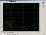
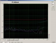
1W / 8Ohm / 1kHz 🙂
Realy interesting
Tanks for posting
What set up do you use for mesurament?
What mosfet family Toshiba Farchild or IRF?
I have tried both and first impression is that the Faichild has more dinamics and is bit more musicall.
I am using FQA12P20 and FQP19 N 20 (could not get the FQA19N20 so I am stuck with the TO220 version but it has been plaiing for months now whitout problems)
Maybe due to different VGS and such.
Tanks for info on ARTA which I have but what I do not have is such a neat low noise floor I am using Audiophile 192 and noise floor level is about 20 dB up especialy on 50 Hz and such.
Most probably noisy motherboard.
Stiil tanks for posting as it gives me one more reason to try and Improve on my set up
Yes I understand that more bias gets you lower distortion with mosfets and F5. But I am curious how much distortion would I get say at 300mA to 600mA per channel to obtain more power in class AB region. I can for sure test lower bias with my upcoming F5 by listening but I am also interested in numbers as I do not have any distortion analyzer.
Maybe an A/B class F5 amplifier doesn't sound as bad? How low has been an F5 biased while mantaining an acceptable grade of distortion?
In other words, does an F5 biased with 100mA or even 50mA per device sound better than, say, a Gainclone?
I have been wondering that since I built my F5. Now that I'm pretty drunk (holy christmas!) I dare to ask this 🙂
Good points there, maybe you should drink more often 🙂.
I was thinking lowering the bias and increasing the feedback. It will not sound as good as with higher bias, but we would have less heat or more power. Everything is just one big compromise.
I was thinking lowering the bias and increasing the feedback. It will not sound as good as with higher bias, but we would have less heat or more power. Everything is just one big compromise.
I am powering tweeters using an F5 biased at 500mA for more than two years .I never felt the need to go higher.It will not sound as good as with higher bias
I have another one biased at 1.3A.
Both sound really nice.
increasing the feedback.
That one i don't quite understand.
Care to elaborate ?
That one i don't quite understand.
Care to elaborate ?
If I remember correctly the open loop gain of F5 is 35dB. Close loop gain is 15dB, so 20sB is used for negative feedback loop. The ratio between open and closed loop gain is set by 47R 5W and 10R resistors.
To increase feedback I would lower 47R to say 20R and overall gain of F5 would drop to less than 15dB, but it is ok for me as I will use preamp with enough gain anyway. Care must be taken about stabilty (oscilation) with increased feedback. Listening test will show if it is worthy increasing the feedback with lower bias current.
gain with 50r (100r//100r) : 10r, is 6times (+15.5dB)
gain with 20r : 10r, is 3times (+9.5dB)
this results in 6dB more feedback.
gain with 20r : 10r, is 3times (+9.5dB)
this results in 6dB more feedback.
20R + 10R = 30R.
Now I dont understand you. I am just talking about open/closed loop gain ration and thus how much negative feedback is used. This ratio is determined by 47R 5W resistor and 10R JFET drain resistor.
30R is half the number of 60R (or 47 + 10, if you like)
With different gain, but equal power output level, losses in the feedback will be higher : save some, lose some.
With different gain, but equal power output level, losses in the feedback will be higher : save some, lose some.
If I remember correctly the open loop gain of F5 is 35dB. Close loop gain is 15dB, so 20sB is used for negative feedback loop. The ratio between open and closed loop gain is set by 47R 5W and 10R resistors.
To increase feedback I would lower 47R to say 20R and overall gain of F5 would drop to less than 15dB, but it is ok for me as I will use preamp with enough gain anyway. Care must be taken about stabilty (oscilation) with increased feedback. Listening test will show if it is worthy increasing the feedback with lower bias current.
Increasing feedback may not be ideal. See NP's post http://www.diyaudio.com/forums/pass-labs/121228-f5-power-amplifier-1112.html#post2762894
The F5 is right on the edge of what of how much feedback you can use
without compensation capacitors. Reducing the feedback on it won't
hurt it at all.
Thank you very much. So change of feedback factor is solved for me then.
If I would add another pair of output mosfets then I should lower the feedback because of more gain in the output stage?
If I would add another pair of output mosfets then I should lower the feedback because of more gain in the output stage?
Maybe an A/B class F5 amplifier doesn't sound as bad? How low has been an F5 biased while maintaining an acceptable grade of distortion?
You can bias the F5 as low is you like. I have one here running at .5 A on my
TV audio and it works fine and the distortion figures are acceptable. I would
not be inclined to use it on my main audio system because it sounds better
above 1 amp.
😎
- Home
- Amplifiers
- Pass Labs
- F5 power amplifier