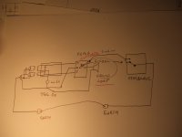
So the audio ground is the output ground? It has to go to the star ground?
Does the input ground have to go to the star ground? Can it share the V-gnd reference on the amp PCB?
Input ground doesnt have to go to the star ground, it can go to the pcb.
Just remember to still have input/JFETground from your pcb connected to star ground.
The three grounds on Cviller PCB (last version i suppose) are directly joined on the PCB.
You can use one for input cable, another one for joining the star ground, the third one forgotten. (Speaker return being wired to the star, not to the pcb.)
You can use one for input cable, another one for joining the star ground, the third one forgotten. (Speaker return being wired to the star, not to the pcb.)
The three grounds on Cviller PCB (last version i suppose) are directly joined on the PCB.
You can use one for input cable, another one for joining the star ground, the third one forgotten. (Speaker return being wired to the star, not to the pcb.)
Thanks, I think I got it now.

Tinitus
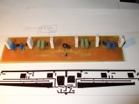
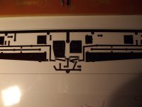
I have enclosed pictures of the mule PCB
and the last version on paper at present.
Regiregi
By I don't think means that it may and it may not ground loops are a pain and are in most cases actually caused by potential difference on the grounds at times just a difference in the wire length may be enough to put a 10 ohm resistors make thing worst but this is just my opinion.
As IMO is much easier to cut one end of the screened cable.
Please don't misunderstand I was just trying to answer one question with the best I know I have also asked why the CL60 is on the ground of the caps on Papa PSU drawing but no answer so far
IMO is not there to stop the ground loop IMO
You feel free to do as you like and if it works I will follow I am always willing to learn new things that’s why we are here is it not?
Attachments

Regiregi I think I have a beter answer to the you think so or you know so
I have cut and paste bit from link in my post 9669.
It does mention that a small difference in potential is the cause of ground loop noise
so 10 ohm resistor make things worst in this rispect
Ground loops, earth hums, buzz and interference. Free data sheet by GB Audio Services
Why ground loop is a problem ?
Ground loops are a mystery to many people. Even college-trained electronic engineers may not know what ground loops actually are. Engineers have either concentrated on power distribution (for the electric company) or on equipment that happens to plug in to the power distribution system. Not much thought has been given to power distribution and equipment as a single entity where ground loops arise.
Ground loops are the most common cause of AC line frequency hum in sound systems. A ground loop in the power or video signal occurs when some components in the same system are receiving its power from a different ground than other components, or the ground potential between two pieces of equipment is not identical.
Ground loop is a common problem when connecting multiple audio-visual system components together, there is a good change of making a nasty ground loops. Ground loops commonly cause humming noise to audio signals and interference bars to picture. Ground loop makes the system sensitive to pick up interference from mains wiring which can lead to erratic operation of the quipments or even damages to the equipments. Audio-frequency groundloop problems are typically in the low millivolt range, so it does not have to be much interference in grounding system to cause problems in audio systems.
Remeber that there is no absolute ground. There is a certain amount of resistance to electrical current between all grounding points. This resistance can change with humidity, temperature, connected equipment and many other variables. No matter how small, the resistance can always allow an electrical voltage to exist across it. The ground wires between wall sockets and power company transformers are not perfect conductors and neither is the shield of your coaxial video cable. If they were, ground loops would not be a problem.
Here is a useful article on the subject:
http://www.diyaudio.com/forums/diya...udio-component-grounding-interconnection.html
http://www.diyaudio.com/forums/diya...udio-component-grounding-interconnection.html
Tanks Variac
Thats a good one
From it 4.1
4.1 - Grounding Rules
Here are some rules to help you plan your grounding structure. The first four rules are from what we learned about interconnecting equipment.
Rule 1: Each of the following must be connected to the system star ground by one and only one route.
All signal references
All power commons
Shields of non-galvanically isolated single-ended inputs and outputs
Safety ground and chassis. The safety ground and chassis should be thought of as a single entity.
The connection may be direct, or indirect through a star-of-stars or buss. This is expanded upon below.
The safety ground and chassis may be connected to the system star ground through a Safety Loop Breaker Circuit.
The “one and only one” part of this rule precludes ground loops. There is no excuse for a ground loop within a single component.
ONE AND ONLY ONE PRECLUDE GROUD LOOPS
I rest my case
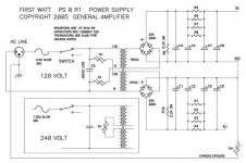
PS 0 R1 PSU RC-calculation
Hi,
I'm just sitting in front of my recently bought cap bank of 12 RIFA PEH 169KO5330Q (33.000uF each) and thinking about how they fit into the PS0 R1 calculation. I'm not sure about the resistor bank R1 - R8. How are they calculated? And how would it affect R9 and R10?
I tried to find a detailed explanation of the PS 0 R1 schematic but couldn't find it 🙁.
Does anybody have an idea how I can implement my caps and what happens to the resistors?
For background information, I'm going to build a 2 channel supply using 1 toroid.
Thx,
Mallard
What is PSO R1?
Attachments
Hi,
I'm just sitting in front of my recently bought cap bank of 12 RIFA PEH 169KO5330Q (33.000uF each) and thinking about how they fit into the PS0 R1 calculation. I'm not sure about the resistor bank R1 - R8. How are they calculated? And how would it affect R9 and R10?
I tried to find a detailed explanation of the PS 0 R1 schematic but couldn't find it 🙁.
Does anybody have an idea how I can implement my caps and what happens to the resistors?
For background information, I'm going to build a 2 channel supply using 1 toroid.
Thx,
Mallard
For the F5 you probably need only 4 of the 33,000 uf caps and leave R1-R8 the same. R9 and R10 too.
Hi,
I'm just sitting in front of my recently bought cap bank of 12 RIFA PEH 169KO5330Q (33.000uF each) and thinking about how they fit into the PS0 R1 calculation. I'm not sure about the resistor bank R1 - R8. How are they calculated? And how would it affect R9 and R10?
I tried to find a detailed explanation of the PS 0 R1 schematic but couldn't find it 🙁.
Does anybody have an idea how I can implement my caps and what happens to the resistors?
For background information, I'm going to build a 2 channel supply using 1 toroid.
Thx,
Mallard
PSUD2
Hi,
I am planning another F5 build but with Toshiba MOSFETs. I have found the attached schematic in one of these threads. Just wanted to check if this is the right one that I am looking at? There seem to be so many discussions on this, just wasn't sure, which one.
Cheers
IF single ended (+/-24V rail) then R11, R12 should be 0R47.
And you should replace P1, P2 with fixed resistors after trimming.
Voltage across R3, R4 more like 3V.
Schematics not proven, so build at own risk.
Patrick
.
Built the F5 (stock circuit) with 2SK1530/2SJ201 outputs instead of IRFs. Only change I made to the circuit as suggested elsewhere by EUVL is to put a 5 ohms resistor in series with the source pin of 2SJ74BL FET. I am using the Thermistors as well as the protection circuit.
Biases up very nicely and rock steady. Currently set the voltage across R11 and R12 at 485mv. Supply rail is +25.6/-25.6V.
I have not listened to the amp yet. Hope it sounds good.
My question is what happens if I push the current up and bias to around 1.2A from the current level like we do with IRFs. Do these Toshiba's get hotter than IRFs at that level?
TIA.
This has probably been asked a bazillion times, but can't find the answer in this tiny thread. I can't find the 2sk1530/2sj201 anywhere, so how about this pair:
FQA36P15
p-channel
36A Idss
150V Vds
19.5S gfs
2550pF Ciss
http://www.fairchildsemi.com/ds/FQ%2FFQA36P15.pdf
FQA28N15
150 Vdss
33A Id
20S gfs
1250pF Ciss
http://www.fairchildsemi.com/ds/FQ%2FFQA28N15.pdf
Could this work?
FQA36P15
p-channel
36A Idss
150V Vds
19.5S gfs
2550pF Ciss
http://www.fairchildsemi.com/ds/FQ%2FFQA36P15.pdf
FQA28N15
150 Vdss
33A Id
20S gfs
1250pF Ciss
http://www.fairchildsemi.com/ds/FQ%2FFQA28N15.pdf
Could this work?
Excuse me for cutting in a little bit. I am preparing to built F5, bought some FETs and came to conclusion that transistor matching between chanels is essential for symetry. But how about two branches of push-pull F5 amp cirquit then ? In the Zen variations - part 5 "The complementary Zen" Nelson wrote: " I use IRFP240 and IRFP9240 as they work fine ................... Matching of Q1 and Q2 is not important". Further more in many post of other people I found that matching N and P FETs doesn't make sense. But in Nelson description of Aleph 30 I found: "A single ended Class A topolgy is approriate, and we want characteristic where the positive amplitude is very, very slightly greater than the negative. For a current gain device, that would mean gain that smoothly incerased with current". The question is: Cant we do it in F5 by N and P careful FET matching with a slight shift in measured Vgs ? Or I just misunderstand the matter?
It does mention that a small difference in potential is the cause of ground loop noise
so 10 ohm resistor make things worst in this rispect
.
If all interconnected equipment has been wired correctly than there is no need for Thermistor, but since there are lot of cowboys around the thermistor is there to reduce the current flow through the earth loop.
With inteconnected equipment there should only be one connection of signal ground to chassis earth.
This is usually done at the amp so everything that is connected to the amp is connected to earth via the amp chassis.
If signal ground is also connected to chassis earth in the cd player (or another piece of equipment) than you have an earth loop. The amount of current flow will be determined by the potential difference between the two chassis earths and the resistance between the two pieces of equipment. If the resistance is high (eg thermistor) between cd player and amp then current around the loop will be low (therfore low or no hum). If resistance around the loop is low then the current will be high (therefore high levels of hum).
If you plan to have signal and chassis earth connected on more than one piece of interconnected equipment you are best using bridge rectifiers to break the loop, otherwise just choose one piece of equipment where signal connects to chassis earth.
I know I have not explained this well but hopefully this makes sense.
This has probably been asked a bazillion times, but can't find the answer in this tiny thread. I can't find the 2sk1530/2sj201 anywhere, ...
http://www.diyaudio.com/forums/swap-meet/161366-matched-toshiba-fets-sale.html
or
http://www.diyaudio.com/forums/vend...you-always-wanted-but-hard-get-they-here.html
to name a few

- Home
- Amplifiers
- Pass Labs
- F5 power amplifier