guys, when i adjust to around 0.55~0.58v across R11/R12. my heatsink is running hotter than 0.60~0.62v. Why its so?
Thanks, what kind of effect will I look for on a scope? 😱 still new to scopes
The oscillation will be very high in frequency - it will look like either a "burst" of thickness on the top of a 1kHz sinewave (any reasonable freq will work) OR the entire sinewave will be made to look THICKER... if you turn your timebase so that the period is shorted (freq you can look at is higher) you will likely see a small sinewave appear in that thickness - assuming you have a scope that triggers on small signals and has the requisite bandwidth (depends on how high a frequency the oscillation is).
Imo you should use the minimum capacitance required to tame the parasitic... of course that value may depend on the amount of capacitance appearing at the load.
You can simulate a capacitive load by putting a cap in parallel with a resistor as a load. Start with a modest size cap to simulate the capacitance of the cables, and work up in value... at HF a shunting cap will look like a short...
Of course there is phase shift WRT frequency with a cap...
A series cap will look like an open at LF and a short at HF.
after you get it to not have a parasitic, then you can try a not too high level of square wave with the same test. A look at the leading edge and overshoot on the top will tell you something more about the compensation and the stability... too much compensation and the leading edge will be rounded over (and hopefully not massively ringing as it would be with a parastic) far too much, which equates back to a HF rolloff. You can stand some rolloff of course.
_-_-bear
I finally got my FETs in and I am wondering how you guys go about matching (or if you bother). I have 20 of each JFETs and 6 of each MOSFET. I read somewhere that there were many more needed (1000 comes to mind) to get a good match. Please reply back with methods, circuits, links etc. so that I can compare what I've read to experienced guys. There's a lot of information out there for a newbie.
Thanks,
Everett
The Jfets are tested for static Idss... the current through them with zero bias on the gate... although since you are maybe more interested in a relative match (a pair of each P & N?) as long as the test rig is the same, the match is ok.
You will likely not get very very good matches with a batch of 20, especially if that is 10 Pch and 10 Nch... but you can still see what is going to be closest to what...
The test is simple enough and really is just a voltage in series with the jfet and a means to measure the current. The specific circuit ought to be online in all sorts of places, including in the Toshiba, Siliconix and other data books...
The Mosfets require a bit more work... you need a similar set up, but with a variable means of adjusting bias voltage, measuring current and supplying some voltage with current behind it.
Hey, wait a second!
I know a good place to do these measurements!
- In the amp! -
yep.
you can just socket one or more of the locations, the jfets are easy, and as long as you don't change anything you can measure their current with a DVM and see which are closest to each other. You don't even need the second half of the circuit connected for that...
The trimmer values should be set identically between P and N ch for testing.
Same with the mosfets, although a socket is tougher - short short leads with small alligator clips will do the trick...
Don't swap with the power on and the caps still charged up...
Easy enough, except for the time and effort... 😀
_-_-bear
I am building a F5. However, I have problem with thermal drift. I use 5K NTC thermistors. Output DC swings up to 100mV and idle current swings up and down too.
I attach the thermistors to the power MOSFET with glue. What is the proper way to mount/attach the thermistors? Would some one help. Thanks.
maybe a mechanical clip with the white silicone heat sink compound between the thermistor and the mosfet?
Also, maybe your heatsink is not large enough and there is rapid shift in the temperature - or alternately there is an air stream that comes and goes varying the thermistor temp at at different rate than the mosfet/heatsink (a phase difference/time constant difference)???
there is also thermally conductive epoxy, but that is sometimes hard to find...
_-_-bear
PS. 100mv is not so bad... you would need a servo to be faster unless the thermal circuit with the thermistor is where the problem is... imo.
Last edited:
I get more stable offset and bias current without thermistors, though the amp then takes a bit longer to warm up - exactly as the pdf notes. In addition, if the ambient climbs above what the amp was biased at, the bias increases and everything gets hotter (and reverse if it becomes colder in your room).
I've noted a bias swing of up to 200mV with ambients ranging from 20 to 30 degrees C, the difference between the coldest winter and a balmy summer here. The thermistors would prevent that I suppose, but I was finding adjusting the amp extremely hard with them in the circuit.
I've noted a bias swing of up to 200mV with ambients ranging from 20 to 30 degrees C, the difference between the coldest winter and a balmy summer here. The thermistors would prevent that I suppose, but I was finding adjusting the amp extremely hard with them in the circuit.
For resistors R5;6;7;8;11;12 I'm using Caddock 930's will 25c/w sinks be sufficient to keep them cool? SorryI'm rubbish with the math.
Are there any U.K builders who would be interested in buying 500VA transformers from Toroidy.pl @58.9euro's each and share postage costs which are 38euros for up to 20kg.
maybe a mechanical clip with the white silicone heat sink compound between the thermistor and the mosfet?
Also, maybe your heatsink is not large enough and there is rapid shift in the temperature - or alternately there is an air stream that comes and goes varying the thermistor temp at at different rate than the mosfet/heatsink (a phase difference/time constant difference)???
there is also thermally conductive epoxy, but that is sometimes hard to find...
_-_-bear
PS. 100mv is not so bad... you would need a servo to be faster unless the thermal circuit with the thermistor is where the problem is... imo.
Thanks Bear.
This is actually the 2nd F5 I built. The last one I built was very stable and the drift was only +-15mV after the amp had been fully burned in. The heat sink, chassis, transformer are all the same as those of the 1st amp I built 7 months ago. You were right about the air stream, since I worked the amp under an air conditioner outlet. After comparing the 2 amps, the only different I found is the brand of thermistors, which I think may be too sensitive to temperature change. The ones on my 1st amp were marked 503(means 5Kohm). The ones in my 2nd amp is of different colour and size & have no marking. The other minor difference is the 0.47ohm resistor type(R11 & R12), which I use 5W wire-wound type this time. They were 3W metal oxide in my 1st amp. I wonder if that would contribute to the swing.
By the way, how to implement an op-amp type DC servo to the F5 circuit?
Thanks again.
Electrolastic
Re
I am building a F5. However, I have problem with thermal drift. I use 5K NTC thermistors. Output DC swings up to 100mV and idle current swings up and down too.
I attach the thermistors to the power MOSFET with glue. What is the proper way to mount/attach the thermistors? Would some one help. Thanks.
Make sure you short the input while biasing🙂
Make sure you short the input while biasing🙂
Thanks Alazira,
Shorting the input or not has minimal difference. I usually plug in 2 shorted RCA plugs when measuring and adjusting.
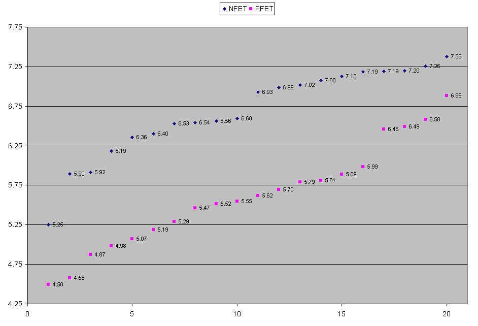
Thanks Bear, I ended up doing Vds=10 and a 1 Ohm source resistor. Here are the results after 80 total measurements (average of two per FET)
I used the 300VA audio version in my monoblocks. I think they are very interesting as quality/price ratio.Has anyone used transformers from Toroidy.pl. I seem to remember that someone said they were going to try them and post results but I havent come across any more posts. I still have another 100 pages to read so maybe I havent found his results yet.
Speak to Tomasz at Toroidy, he's very friendly.
Attachments
Yes Tomasz at Toroidy is a nice guy; there going to make me transformers with 240 volt primaries as my mains supply regularly hits 245 volts +
near Lincoln your tolerance on mains supply voltage is 216Vac to 254Vac. The lower limit will probably never be reached other than during a fault situation. It used to be 226Vac and you can reasonably expect your range to be between 226Vac and 254Vac
Adding a few turns to the primary winding will make a difference particularly since the combination of high input voltage and low mains frequency takes all universal transformers right to the edge of the production/design compromises.
Better would be a tapping at 230Vac & 240Vac.
Best of all would be one primary at 120/125Vac and the second primary at 115/125Vac.
This would allow you to select any voltage from 235Vac to 250Vac in 5V increments.
The two extra taps will probably cost more, but may be worth it to you.
Note that none of these options allow use in a 110/120Vac region.
Thanks for the reply Andrew. I'll go for the straight 240V primary as I used to use some potted Avel Lindberg transformers on Pass A40's years ago and they were as silent as the grave. I still have them but unfortunately at 22-0-22 secs they are no good for the F5 as I'd like to keep the power supply as simple as possible.
Regards Keith
Regards Keith
Better would be a tapping at 230Vac & 240Vac.
Best of all would be one primary at 120/125Vac and the second primary at 115/125Vac.
This would allow you to select any voltage from 235Vac to 250Vac in 5V increments.
This is a very interesting hint.
I suffer from different main voltage too. I live near an industrial site and I see my main from 220V to 240V along the day or the week (Sunday and evening is usually high). When main is around 220V, my V+ and V- are around +-20.5Vdc.
standard 110/115 +110/115 Vac primaries would do very well for Continental countries. These two extra taps add a lot of adjust-ability.
But most transformers come 115+115 or 230 now.
Best of all for a universal transformer would be 110/115/120 +110/115/120 primaries which can be used in any 110/120 and 220/230/240Vac country.
Those four extra tappings are sometimes seen in expensive transformers.
But most transformers come 115+115 or 230 now.
Best of all for a universal transformer would be 110/115/120 +110/115/120 primaries which can be used in any 110/120 and 220/230/240Vac country.
Those four extra tappings are sometimes seen in expensive transformers.
Last edited:
Yes Tomasz at Toroidy is a nice guy; there going to make me transformers with 240 volt primaries as my mains supply regularly hits 245 volts +
Choose audio version, more expensive (around +50%) but better (impregnated, shield between pri/sec, selected core).
Another hint, ask for quotes in zloty and maintain the currency change on your side (PayPal or credit card). I suspect price are lower in this way.
Those four extra tappings are sometimes seen in expensive transformers.
At Toroidy you can ask whatever you need. You pay for that, of course.
I bought a power transformer some months ago for a future KT88 project and they made it as I asked, price was markedly lower than the same Hammond model.
Yes I opted for the audio grade transformers although I never thought to ask for a quote in zloty. Anyway they are cheaper by 25-40% than two U.K suppliers of audio grade transformers even with there 38 Euros shipping. just wish I needed more transformers or for other U.K builders to do a joint buy.
- Home
- Amplifiers
- Pass Labs
- F5 power amplifier