I will most certainly be auditioning a pair of 1990 MG2.6/R's on a F5.
Rated for 87dB sensitivity and 4.7 ohms, I cannot imagine the ribbons will disappoint with an F5, I hear the top-end is supernatural on the F5 - that is also how I could describe those foil ribbons - what a match!
I hope so. I have a pair of them and am just starting to build an F5 for dedicated use on the foil ribbons. Bypassing the passive crossovers was the first step. And I still have trouble believing how big a difference that made. The F5 looks to me like a really good choice for the ribbons. At least I am going to find out. Crossover point is about 750 Hz and impedance is aprox. 3.2 ohms. And they are far more efficient than the bass panel. If this works out as well as I hope it does, then I will have to find the complimentary amplifier for the bass panels. Which I don't want to think about yet. But those are a whole different animal. I suspect that will ask for maybe 200 Watts into 4 Ohms to get all of the goodness out of those. Perhaps less now that the passive crossover isn't taking its tax on the supplied power.
Last edited:
bobo, that will not make an efficient heatsink for a large size like is needed in this amp.
I do not agree.
This is only a matter of scaling.
For instance, stack 6 plates 0.2cm x 40cm x 15cm,
spaced by 5 plates 10cm x 15cm x 0.5cm.
Bolt them firmly using white goo.
Use them as two sides of the casing.
It will do.
maybe... there needs to be sufficient fin area, and sufficient spacing between the fins to permit proper air convection minus the losses between the layers... I think it needs to be bigger and more layers... if the losses between the layers are not too bad.
_-_-bear
_-_-bear
Hi,
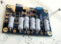
I make layout for my F5 board, please help me to check this layout, assuring there is no faulty on it. I havent edit the SK370 layout, the correct one is reverse it. Also about the thermistor, its better if placed near output transistor.
Thanks before
I make layout for my F5 board, please help me to check this layout, assuring there is no faulty on it. I havent edit the SK370 layout, the correct one is reverse it. Also about the thermistor, its better if placed near output transistor.
Thanks before
Attachments
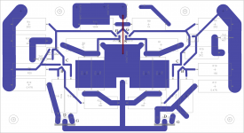

i am wondering, there is +24 -24 and Gnd after CRC, the picture shown above don't connect anything to Gnd after crc, is it no need to connect the Gnd from crc to the Gnd of F5 board??
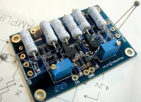
here is mine.
An externally hosted image should be here but it was not working when we last tested it.
i have a bunch of stupid questions, hope you all don't mind
my transformer used is E transformer which lead out 18 0 0 18, in before i am too stupid to connect both 0 0 together and into the Gnd of the CRC, and smoke coming out from the wires :O so end up i don't connect anything to both 0. Or is it wrong anything?
Last edited:
chchyong89;
On mine the F5 ground goes to speaker negative and input negative only, CRC ground goes to chassis earth, 18 0 to 1 rectifier and the other 18 0 to other rectifier with the 2 positive outs of rectifier joined together to CRC + and same with - from rectifier, hope that makes sense.
On mine the F5 ground goes to speaker negative and input negative only, CRC ground goes to chassis earth, 18 0 to 1 rectifier and the other 18 0 to other rectifier with the 2 positive outs of rectifier joined together to CRC + and same with - from rectifier, hope that makes sense.
Psu (CRC) ground is connected to F5 board.(Green wire)
Generally, the outputs of a transformer are 0-18-0-18 and not 18-0-0-18.
To check, connect the two presumed 0 together and then measure voltage across the two 18. You should read 36v. As long as you do not short a winding, there is no risk.
Generally, the outputs of a transformer are 0-18-0-18 and not 18-0-0-18.
To check, connect the two presumed 0 together and then measure voltage across the two 18. You should read 36v. As long as you do not short a winding, there is no risk.
never experiment with transformer connections without a mains bulb tester feeding the primary.
post7766.
are the two double insulated wires coming from the transformer, the mains input?
If yes, then they should be double insulated all the way back to the mains fuse and to the IEC input socket.
Twist all the wire pairs into and out of the transformer to minimise the radiated fields.
are the two double insulated wires coming from the transformer, the mains input?
If yes, then they should be double insulated all the way back to the mains fuse and to the IEC input socket.
Twist all the wire pairs into and out of the transformer to minimise the radiated fields.
An externally hosted image should be here but it was not working when we last tested it.
here is my transformer lookalike
i am using two 330W E transformer, one for each + 24 and - 24 terminal. and after the crc is 25~26Vdc after measured.
u mean both the black "0" should go back to the earth?
chchyong89;
On mine the F5 ground goes to speaker negative and input negative only, CRC ground goes to chassis earth, 18 0 to 1 rectifier and the other 18 0 to other rectifier with the 2 positive outs of rectifier joined together to CRC + and same with - from rectifier, hope that makes sense.
i am using the example shown by
An externally hosted image should be here but it was not working when we last tested it.
i connect both 18Vac into one rectifier, which the 0 where to go is still a question😕
do not connect any rectifiers to the untested transformer.
Just measure the AC voltage at the wire ends.
Just measure the AC voltage at the wire ends.
can i ask more one question, actually is it 330watt enough for both channel?( although nelson recommend 200watt per channel)
i thinking to use only single transformer to power up this F5. i don't wish to waste my 4 pcs of same transformer.
i thinking to use only single transformer to power up this F5. i don't wish to waste my 4 pcs of same transformer.
can i ask more one question, actually is it 330watt enough for both channel?( although nelson recommend 200watt per channel)
i thinking to use only single transformer to power up this F5. i don't wish to waste my 4 pcs of same transformer.
Hi,
The production F5 uses a 300VAC transformer, so your 330 will be fine. However, more is always better🙂
- Home
- Amplifiers
- Pass Labs
- F5 power amplifier