Thats why you should change the direction of you dmm - the dmm measures resistance by applying a small voltage or current in one direction, so the active devices in the path may change your readings. I have usually seen minimum values very close to 0 ohm, but according to the data sheet, it might be 50ohm.
www.bourns.com/PDFs/3296.pdf
www.bourns.com/PDFs/3296.pdf
Aren't P and N channel mosfets inverted?
My Q6 and Q5 are facing opposite directions-I followed the datasheet for E D C
Cv-when you said try measuring both ways, i thought you meant to turn the pot the opposite way 😱 I was tired. I'll try swapping the probe polarity when i get home though
Hi,
the light bulb tester will not pass sufficient current to allow bias setting of a ClassA power amp.
If the bias setting pots are set to zero, the bias current is also zero.
The bulb tester will allow one to power up the amp in this zero bias condition.
As the bias adjustment pot is turned, the bulb will start to glow.
Remove the tester and connect the power amp direct to the mains.
Complete the setting of the bias current.
If the tester glows brightly, then that indicates that the amp is drawing high current. Check the voltage reaching the transformer primary. Check the voltage at the smoothing capacitors. These two voltages will tell one a lot about what the problem is.
AndrewT, very nice suggestion. Perhaps you could post this once a week to keep it fresh in the collective memory? 😀
setting the pots to minimum implies lowest resistance to me. So when adjusting you will be adding resistance to reach the desired readings?
and with a virtually constant current passing through the set of parallel resistors the Voltage across the resistors increases.setting the pots to minimum implies lowest resistance to me. So when adjusting you will be adding resistance to reach the desired readings?
That increased voltage is applied to the Vgs of the output FET.
More resistance turns on the FET.
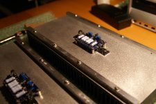
thermistors
Does anyone know the appropriate distance between the thermistors and the mosfet's ? I can imagine the it is important for biasing the amp.
Does anyone know the appropriate distance between the thermistors and the mosfet's ? I can imagine the it is important for biasing the amp.
Does anyone know the appropriate distance between the thermistors and the mosfet's ? I can imagine the it is important for biasing the amp.
0mm
Ok, perhaps I should have elaborated...
Papa usually recommends to glue the thermistors to the mosfets.
Papa usually recommends to glue the thermistors to the mosfets.
That close?
I have them about 1/2 inch above them and having some trouble getting the bias stable.
I have them about 1/2 inch above them and having some trouble getting the bias stable.
That close?
I have them about 1/2 inch above them and having some trouble getting the bias stable.
Many have gotten the bias reasonably stable even without them. You probably have a thermal problem. You need to adjust the amp with the lid on, or at least make sure that the dc offset is low when the lid has been on for a while.
You need to adjust the amp with the lid on,/QUOTE]
ok, that is clear.
I don't have a front and a back either, that would explane a lot.
But what kind of glue would you use?
you don't need glue
just look at F5 pictures floating around .
isolate leads of thermistor , and lean it to mosfet case
just look at F5 pictures floating around .
isolate leads of thermistor , and lean it to mosfet case
Wow the search thread feature is nice:
http://www.diyaudio.com/forums/pass-labs/121228-f5-power-amplifier-84.html#post1516754
I would guess that your problem comes from turning the pots too far each time. Try to work in half measures - if your dc is 40mV lower it to 20mV and see what happens. If you go directly for 0mV, the amp will punish you. Just like with the ladies! 😀
ok, ok,
I am somewhat impatient.....
......

you certainly are - 6M for two pics ........
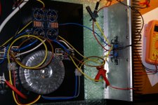
you already have isolated leads of thermistors ; just push them to mosfet case , maybe even with blob of thermal goo in between
if you want - use RTV silicone or any other sort of silicone like glue , but be careful - to not mess direct contact of NTC with mosfet case
so, i'm 99% sure my trimpot is shot...when i measure P2 from pin 2 to 3 I get 72 ohms (min) vs the other pot (P1) I get .3 ohms
The other channel I get .3 ohms for P1 and .4 ohms for P2
I had one of my pots installed backwards at first, so i had to desolder it, flip it, and resolder it, and I can't tell which one it was, So I'm putting 2 and 2 and assuming I damaged something inside the trimpot.
The other channel I get .3 ohms for P1 and .4 ohms for P2
I had one of my pots installed backwards at first, so i had to desolder it, flip it, and resolder it, and I can't tell which one it was, So I'm putting 2 and 2 and assuming I damaged something inside the trimpot.
- Home
- Amplifiers
- Pass Labs
- F5 power amplifier