i would run 12-14 AWG wire per pole for each V+, V-, and 2 ground returns (4 poles total per channel) from each monoblock back to the star ground in the PS. i guessing at this point each umbilical will be around 4 ft. any issues with output impedance and ground returns? would adding more caps be beneficial? my house AC is pretty stable, but would i benefit from a regulated PS in this scenario?
i would prefer the remote PS option, if only for the ease of construction and flexible "space management" options afforded. thanks!!!
Put another bank of capacitor inside the amp case.
I would go for at least 60,000uF per rail per channel.
So if it is mono-blocks, then you've got another 120,000uF in each amp case.
Then in the power supply case put in around another 120,000uF (60,000uF per rail) per channel.
You can put in more if you like, it is up to you.
1A ? wouldnt that be pr device, so that you actually have 2A with double pairs, on each side ?
Heat ?
Could also be oscillation ?
Hi Tinitis,
Yes, 1A per device for the renesis double pairs, so 2A per side. The extra heat from more mosfets is understandable, but I was more concerned about the 15C difference. On the N side one was 82C and the other 97C. For the P side I measured 89C and 99C.
Perhaps I'll set up a poll for those who have registered and paid - that would probably be most fair. 😉
..
I think the way you have suggested is the preffered way (simple). I would probably just go with that, as it is meant to be an option not the default set up.
Then if people want to try it then it is up to them to find the correct jfets.
I think Andrew gave some suggestions.
This will make your job easier.
Hi Tinitis,
Yes, 1A per device for the renesis double pairs, so 2A per side. The extra heat from more mosfets is understandable, but I was more concerned about the 15C difference. On the N side one was 82C and the other 97C. For the P side I measured 89C and 99C.
The devices shouldn't go higher than 60 degrees Celsius for long term reliability.
99 degrees C is way too high. turn the bias down now before they blow.
It is possible you may not have them mounted correctly (ie flat). If your heatsink is at 60 degrees and the devices are around 90 degrees then you have a problem.
Last edited:
but that is precisely the point I am trying to get you to understand.
DeltaI times Rout equals deltaV
The output voltage is modulated exactly the same amount whether it is a ClassA amp or a ClassAB amp that delivers the same output current.
The shape of the modulation differs.
If the shape is different than it is not the same now is it??
As I am trying to get you to understand, the AMOUNT of variation is not the only thing that may be of importance?
_-_-bear
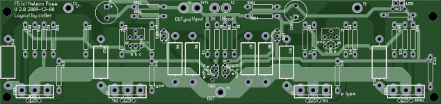
My F5 layout including the cascode posted by Zen Mod earlier.
I found a way to avoid jumpers or telling people to cut traces...
If you look closely at the area around the jfets you can see that I have added two holes. These holes are to be used for the cascode version, so all you need to do is bend the legs of the jfets slightly. 😎
I found a way to avoid jumpers or telling people to cut traces...
If you look closely at the area around the jfets you can see that I have added two holes. These holes are to be used for the cascode version, so all you need to do is bend the legs of the jfets slightly. 😎
Attachments
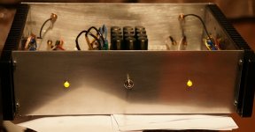
Yesterday I finally fired up my amp!! Its working, generator signal on the scope looked good. Sounding tests will be preformed today i hope (after bias final setting and the observation of heat sink temperature)
Thanks to member Apassgear for PCB layout in this thread and of course thanks to Mr.Pass!!😎
And thanks to other F5 builders!
Thanks to member Apassgear for PCB layout in this thread and of course thanks to Mr.Pass!!😎
And thanks to other F5 builders!
Attachments
Last edited:
Put another bank of capacitor inside the amp case.
I would go for at least 60,000uF per rail per channel.
So if it is mono-blocks, then you've got another 120,000uF in each amp case.
Then in the power supply case put in around another 120,000uF (60,000uF per rail) per channel.
You can put in more if you like, it is up to you.
thanks - however, it's not the answer i was looking for 🙂. i guess i'll stick with a single chassis design.
yes!the AMOUNT of variation is not the only thing that may be of importance?
Yes, polishing by hands
Ouch.
Attachments
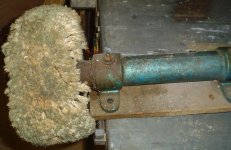
Nice tool for polishing. Most of the my tools in my summer house garage, so in my apartment, unfortunately, not enough space for all the instruments and tools.....
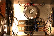
if someone interested in specification of my F5 :
600VA 2x17 VAC trafo (because in my country i cant get 400 or 500VA, just 300 and 600 - so , i go for the bigger one)
6x10 000uf @ 35V caps per rail.
Output transistors - IR and Vishay pair.
famous Papa 22K modd 🙂
Heat sinks from old soviet radio translation amplifier.
DIY case, PCBs.
Last edited:
if someone interested in specification of my F5 :
600VA 2x17 VAC trafo (because in my country i cant get 400 or 500VA, just 300 and 600 - so , i go for the bigger one)
6x10 000uf @ 35V caps per rail.
Output transistors - IR and Vishay pair.
famous Papa 22K modd 🙂
Heat sinks from old soviet radio translation amplifier.
DIY case, PCBs.
I think that 600Va is better too.
I used for my F5 a IR output transistor too, but want to try the FQA ( fairchild).
I recieved these transistor yesterday .
I will compare the sound to IRF when I have a little time.
Attachments

Last edited:
I guess it is slightly OT, how to make faceplates...
but it is simply a matter of progressively finer grit Al Oxide wet/dry paper via a flat surface and/or parallel strokes. Water or oil will keep the grit from clogging, but you have to clean between steps and when ur done.
Alkaline cleaners, like "Mean Green" (USA, east coast) or even BBQ cleaners, floor strippers tend to brighten aluminum when cleaning... test on scrap first. Dishwasher detergent also cleans and seems to brighten aluminum somewhat.
If you go for a fully polished aluminum faceplate (I would not, because it shows every fingerprint) you don't have to be quite so careful in being parallel, just flat, and then buff using "white" compound and motorized buffing wheel.
You can do a nice "brushed" finish on aluminum using a relatively coarse heavy grit of "Scotchbrite" (or equivalent) pad, again parallel strokes.
If you have a local metal shop they might throw it through a "Time Saver" machine that does the parallel scratching bit and keeps things parallel.
A somewhat more durable finish can be obtained via a raw etch in Lye. The ARRL handbook shows this (or at least older editions did...), but keep in mind that when you etch (or go for anodizing) the "grain" you imparted is reduced substantially, so if you want a grained look, go for one or two grits to the coarser before etching. Of course the Lye etched look is not bright polished.
I've gotten away from raw aluminum myself because it really does not hold up over time, and will corrode and show fingerprints.
There are requirements for anodizing, and that solves the corrosion and fingerprint problems but is not so simple and not cheap for single panels, unless you do the anodizing process urself, which again is not so simple or cheap for one off jobs.
There are other attractive materials for front panels. If you need shielding, backing with a metal plate or covering with the adhesive backed copper tape will do that job.
Of course, work with whatever you have to work with...
Oh, fwiw, a front panel of brass can be bright polished and then lacquered. You can get finished brass and aluminum in the form of "door kicks" from most building supply houses and hardware stores, of course you will have to cut it without messing up the front finish.
_-_-
Last edited:
There is nothing special - like described here - How to polish aluminum for motorcycles to chrome like finish
using hand (immortant with last fine grade sand paper 2500) you can more easily control the speed and pressure and no to "burnt" aluminium . The last polish to be gentle and you often need to change sanding paper.I do not want the mirror surface, therefore,I do not use this soft discs (which are placed in drill for example) ..
using hand (immortant with last fine grade sand paper 2500) you can more easily control the speed and pressure and no to "burnt" aluminium . The last polish to be gentle and you often need to change sanding paper.I do not want the mirror surface, therefore,I do not use this soft discs (which are placed in drill for example) ..
Fwiw, IF you are going to anodize, never use steel wool to polish aluminum. It leaves steel in the surface, and that messes with the anodize process...
Someone suggests that in osscar's link...
_-_-
Someone suggests that in osscar's link...
_-_-
Ouch.
I'm guessing the other end is connected to gears, chain and pedals....

- Home
- Amplifiers
- Pass Labs
- F5 power amplifier