I was only able to bias it to 1A before hitting 50C on the heat sink (vs 1.3A and 41C with single pair Fairchild parts).
1A ? wouldnt that be pr device, so that you actually have 2A with double pairs, on each side ?
Heat ?
Could also be oscillation ?
i'm vacillating between building the PS chassis remote with monoblocks, or a single chassis design. my PS is the basic Pi filter per the schematic in the F4 article, with 132,000uF and a 500VA TX. i have these Neutrik speakON connectors NL8FC Neutrik Audio/Video Connectors, capable of 30A and 8 poles. i would run 12-14 AWG wire per pole for each V+, V-, and 2 ground returns (4 poles total per channel) from each monoblock back to the star ground in the PS. i guessing at this point each umbilical will be around 4 ft. any issues with output impedance and ground returns? would adding more caps be beneficial? my house AC is pretty stable, but would i benefit from a regulated PS in this scenario?
i would prefer the remote PS option, if only for the ease of construction and flexible "space management" options afforded. thanks!!!
i would prefer the remote PS option, if only for the ease of construction and flexible "space management" options afforded. thanks!!!
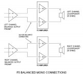
F5 Balanced Mono Wiring...
Hello All,
I've now got all the bits needed to make a pair of F5 amplifiers.
I have a balance source (Buffalo 32s) and relatively inefficient speakers, so was going to configure the F5s in a balanced mono configuration.
Before I start wiring up the boxes, I want to make sure I've got the configuration correct.
Could someone please confirm that the attached wiring diagrams are correct. The 2nd image is borrowed from the First Watt F4 Operation and Service Manual.
I'm just a bit confused as I thought with a balanced signal, the amplifying block should be amplifying the difference between the positive phase and the negative phase... Not against the 'ground' signal. Then again, I suppose with the 'ground' being common to both amplifying blocks, perhaps it is.
Thanks in advance!
Regards,
alex
Attachments
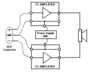
This is correct. Though, one grounding point would be sufficient to avoid to create a ground loop.
Hi Cviller,
About cascoding and your new pcb:
If you choose the bjt option (two reistors ad one more cap) this could be used easily with Jfet either.
The opposite, no.
About cascoding and your new pcb:
If you choose the bjt option (two reistors ad one more cap) this could be used easily with Jfet either.
The opposite, no.
but that is precisely the point I am trying to get you to understand.That they modulate the same absolute value of current is not the point I am making.
DeltaI times Rout equals deltaV
The output voltage is modulated exactly the same amount whether it is a ClassA amp or a ClassAB amp that delivers the same output current.
The shape of the modulation differs.
bf244b or 244c or the alternative pin out bf245b or 245cappears to be a matter of finding the correct jfets high Vp and high current
The BC option could probably be the most sensible option, but I just like the simplicity of the jfet option.
keep dissipation per mosfet up to 50W
Cool.
ZM, with 150 ohm feedback resistors, does that up the gain any?
I am considering lowering the gain in next F5 rendition. I like the F3 like gain at 12db. Don't want to ruin the sound though.

Cool.
ZM, with 150 ohm feedback resistors, does that up the gain any?
I am considering lowering the gain in next F5 rendition. I like the F3 like gain at 12db. Don't want to ruin the sound though.
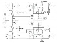
it will not "sound" - that schematic is deffective

ratio of fdbck resistors is same as in origigi Papamp .
50:10 ~ 75:15

that schematic is deffective
Up to 45V rails, that would be like 100watt

Last edited:

it will not "sound" - that schematic is deffective
ratio of fdbck resistors is same as in origigi Papamp .
50:10 ~ 75:15
The amp will sound differently if you change Source resistor to 15R, because it will make Id lower.
For example:
If we have a k170 with Idss=8.7mA the Id with 10R Rs will be 6.6mA, and with Rs=15R the Id will be 5.9mA. That's a small change, but it will affect the sound.
Although, people with fullrange speakers won't be able to hear the difference anyway
kwayzee Serb - it will sound different anyway - because of raised xconductance in output
edit - for my liking - 2SJ109V and 2SK389V on input are better way ... then I can omit output mosfets, and drive my fullrange speakers ditto from input stage ......
edit - for my liking - 2SJ109V and 2SK389V on input are better way ... then I can omit output mosfets, and drive my fullrange speakers ditto from input stage ......
Last edited:
keep dissipation per mosfet up to 50W
Thanks for the schem! Looking forward to hear if AR2 gets it up and running.
Hi Cviller,
About cascoding and your new pcb:
If you choose the bjt option (two reistors ad one more cap) this could be used easily with Jfet either.
The opposite, no.
Exactly!
But I think I'll make the board stock F5 as default and then people will have to cut a trace to get the cascode version.
bf244b or 244c or the alternative pin out bf245b or 245c
Nice but are there any P-versions and I'm afraid the cut off voltage is too close to zero to accommodate the toshibas.
cviller,
What if you allowed a jumper so that we jumper for stock F5 and we leave normal for cascode? Easy for us to cut a small piece of copper to solder in. Tidier than cutting but just as easy I suppose.
Uriah
What if you allowed a jumper so that we jumper for stock F5 and we leave normal for cascode? Easy for us to cut a small piece of copper to solder in. Tidier than cutting but just as easy I suppose.
Uriah
Perhaps I'll set up a poll for those who have registered and paid - that would probably be most fair. 😉
But it doesn't really matter, I just figured it would be easier to explain to people doing the cascode version that they need to do a few tricks rather than to the probably less experienced crowed that they need to insert jumpers...
But it doesn't really matter, I just figured it would be easier to explain to people doing the cascode version that they need to do a few tricks rather than to the probably less experienced crowed that they need to insert jumpers...
Thanks for the schem! Looking forward to hear if AR2 gets it up and running.
......
as usual - give my pair of pcbs to someone who will build it , actually

Hi
I have decided to make another gb run of the f5 pcbs, but instead of making the same again I have also decided to make the boards longer.
But all that extra space made me want to include some cool options for people to try out, which leads me to the question.
Has anyone tried cascoding with jfets as in the attached schematic? I have searched the thread, but only found the cascoding done with bjts.
Not to rain on any parades, but these cascoded schematics with higher voltages don't look anymore like an F5, they are looking more like a pretty standard power amp, except lacking the driver stage??
Dunno, thinking out loud...
And, was the problem with cascoding two K170s that the upper one does not supply sufficient current??
_-_-silly bear
Yeah, it is not the F5 any more, but as I have mentioned many places, it should be as an option and not the default.
The K170 problem is due to the lower not getting enough voltage to operate if the cut off voltage of the upper is too close to that of the lower (if I quote borbeley correct).
- Home
- Amplifiers
- Pass Labs
- F5 power amplifier