hi
dose blanced f5 decrease noise?(like Differential input amp )or it just for more power?
Common Mode Noise dont influe on f5?😕
dose blanced f5 decrease noise?(like Differential input amp )or it just for more power?
Common Mode Noise dont influe on f5?😕
JimT said:I have the Keystone 4661's and put a IRFP240 on it to check. The two small holes in the mica are low enough down that they are under the plastic part of the case just at its lower edge. The holes should not be an electrical problem.
Jim
Jim, thanks for checking!🙂
Regulated Supply
Has anyone built up an F5 fed from a regulated supply?
I was wondering if the advantages of a regulated supply would be heard in this case. The noise figure specs seem to be pretty good using a simple symmetric supply. But maybe with regulation the thing would become dead quiet.
Thanks,
Steve
Has anyone built up an F5 fed from a regulated supply?
I was wondering if the advantages of a regulated supply would be heard in this case. The noise figure specs seem to be pretty good using a simple symmetric supply. But maybe with regulation the thing would become dead quiet.
Thanks,
Steve
Nelson himself suggested the possibility, and pointed to a couple of regulated supplies in the Zen articles.
I've been pondering the Teddy Pardo Powerreg from pinkfishmedia, but don't know if the pass resistor can really stand up to the large current demands of the F5. Let us know if you give a regulated supply a try.
I've been pondering the Teddy Pardo Powerreg from pinkfishmedia, but don't know if the pass resistor can really stand up to the large current demands of the F5. Let us know if you give a regulated supply a try.
regulated supply
I'm thinking about it. I'm a little hesitant because of the extra heatsinking for the power supply. It might almost be worth it to put the power supply in it's own seperate case and feed the amp via an umbillical.
The amp itself could be in a smaller case of course.
I have to ponder a bit more.
Steve
Re: Regulated Supply
The noise is pretty low -- NP indicated 100uV with 29mF filter caps --
If you use a regulator, the pass devices should be capable of handling 5 amps peak on each side.
sekess said:Has anyone built up an F5 fed from a regulated supply?
I was wondering if the advantages of a regulated supply would be heard in this case. The noise figure specs seem to be pretty good using a simple symmetric supply. But maybe with regulation the thing would become dead quiet.
Thanks,
Steve
The noise is pretty low -- NP indicated 100uV with 29mF filter caps --
If you use a regulator, the pass devices should be capable of handling 5 amps peak on each side.
regulated supply
If each device would be capable of 5 amps peak per side and the rule of thumb for a regulated supply is to give it at least 10 times the capacity of what the ampis rated for, then I would need 3 pairs of MOSFETs in the supply -- since the amps output devices are drawing 1.3Amps per device at idle.
Does this sound about right?
If this is correct, that amounts to pretty huge power supply for a 25 watt per channel amplifier.
Steve
Oh wait,
I think I misunderstood what you said. Your saying that the capacity of the supply MOSFETs should be 5 amps for the F5 -- in that case, I'd be ok with one pair of IRFP's per power supply per channel.
Steve
I think I misunderstood what you said. Your saying that the capacity of the supply MOSFETs should be 5 amps for the F5 -- in that case, I'd be ok with one pair of IRFP's per power supply per channel.
Steve
Of course dissapation can be fairly low in regulators , depending on what voltage your raw supply is at . You may not need that much sinking. Are you thinking tight regulation or mostly capacitance multiplication?
I was thinking capacitance multiplication. But, I have not decided yet. I was trying to get a feel for what a regulated supply build would entail and if the extra effort would yield a significant enough improvement in the sound.
amp-guy said:Of course dissapation can be fairly low in regulators , depending on what voltage your raw supply is at . You may not need that much sinking. Are you thinking tight regulation or mostly capacitance multiplication?
The amount of heat you have to dissipate is the drop in voltage times the current, with some windage for peak vs average. My point was that a lonely LM317/337 probably wouldn't be up to the task.
sekess said:an F5 fed from a regulated supply
An input choke transformer power supply has additional features and less downsides, imdo.
Maybe I misunderstand the previous post, but you cannot use a single LM3x7 regulator for the F5. The LM3x7 regs have a current limit of about 1.5A. Sure you can parallel them, but why do so, if a single LT1083 is up to the job? 😉
You can wind your own choke if you want to go exotic, remember to deal with the additional magnetic field though. Improperly placed it can nicely reduce your dynamic range - but it's very probably not noticable...only measurable. 😀
Have fun, Hannes
You can wind your own choke if you want to go exotic, remember to deal with the additional magnetic field though. Improperly placed it can nicely reduce your dynamic range - but it's very probably not noticable...only measurable. 😀
Have fun, Hannes
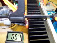
F5 build on one Conrad-151 hsink
Finally got to test the boards on one Conrad MF35-151.5 heat sink to test its
ability to cool two F5s for a possible balanced configuration. If it is too hot,
Nelson has commented that the bias could be reduced to lower hs temp.
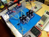
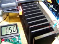
The amps biased up easily enough. The current is 1.1775A on each mfet, {0.683v/0.58ohms}. So far, after two hours the temps range from 61°C, 57°C, 50°C going from the center of the hs to the edge.
As can be seen in the pics the mfets are clamped high up on the sink and the middle two could be separated more. Also, the ambient basement temp is 15.6°C {60°F}.
Hope to give a listen on junk drivers tonight and if it's behaving maybe hook them to a pair of Seas Thors fed directly with the Buffalo Sabre/Ivy w/volumite.
Finally got to test the boards on one Conrad MF35-151.5 heat sink to test its
ability to cool two F5s for a possible balanced configuration. If it is too hot,
Nelson has commented that the bias could be reduced to lower hs temp.
The amps biased up easily enough. The current is 1.1775A on each mfet, {0.683v/0.58ohms}. So far, after two hours the temps range from 61°C, 57°C, 50°C going from the center of the hs to the edge.
As can be seen in the pics the mfets are clamped high up on the sink and the middle two could be separated more. Also, the ambient basement temp is 15.6°C {60°F}.
Hope to give a listen on junk drivers tonight and if it's behaving maybe hook them to a pair of Seas Thors fed directly with the Buffalo Sabre/Ivy w/volumite.
Attachments
Attachments
Peter Daniel said:I completed my new monoblocks as well, and I'm very happy with the amp; connected directly to a source (no line stage, no attenuator) this is probably the best amp I had in this system.
😎 Cool, your builds are always a work of art.
Peter,
Tell us about your configuration :
which circuit, rail, bias
what FETs
what passives, etc.
Patrick
Tell us about your configuration :
which circuit, rail, bias
what FETs
what passives, etc.
Patrick
After initial impressions with my first amp I got confident enough that this could be the amp to replace what I had previously. I've built it over last weekend using only the components I had already in stock, so I didn't have much opportunity to experiment with parts selection, but after all is done, it seems like parts choices worked out fine.
The main point of my build was to bring filter caps as close to the amp as possible. I used Vishays S102 for series resistors and Caddocks for input shunt ans feedback. In feedback I have 2 x 150R per side and IIRC the gain is approx 17.5dB. Didn't use current limiting as I'm pretty sure the amp sounds better without it, didn't use thermistors as they don't make much difference in a well ventilated chassis.
My intention when designing those PCBs was the option to place the boards between two vertical closely spaced heatsinks, one device per heatsink:
The copper wire bridging two caps is the main star ground, this is where speaker output and signal ground (from the input section) are connected.
Initially, I planned on 2 x 10,000uF Jensens only in the amp enclosure and the rest of the PS separately, but after initial inspection it seemed like the other 2 caps would fit too ( 2 x 15,000uF)
The two banks of caps are connected p2p with Cardas wire, taking into account 4 pole configuration. I initially planned on Caddocks power resistors but didn't notice that values were wrong. I ended up with 0.22R 5W Mills in series between caps. They run reasonably warm only. As suggested, input and output are separated
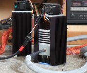
I used heatsinks that I purchased 15 years ago, because of special slots and threaded inserts, coming with a complete enclosure was reasonably easy, heatsinks are approx 5 x 11" and they probably run at 40 deg or so. Bias is set to 1.3A. I wanted that chassis to be well ventilated so the components, especially caps don't overheat.
The slotted cover plates that can be moved up and down for easy access for the amp adjustement. Transformers were originally planned to install separately, but I figured out why not simplify things and put then on top; I might later install them inside the amp, but I probably won't bother 😉
With 300VA, 2 x 18V Plitron per channel, the rails are approx 24V
The main point of my build was to bring filter caps as close to the amp as possible. I used Vishays S102 for series resistors and Caddocks for input shunt ans feedback. In feedback I have 2 x 150R per side and IIRC the gain is approx 17.5dB. Didn't use current limiting as I'm pretty sure the amp sounds better without it, didn't use thermistors as they don't make much difference in a well ventilated chassis.
An externally hosted image should be here but it was not working when we last tested it.
My intention when designing those PCBs was the option to place the boards between two vertical closely spaced heatsinks, one device per heatsink:
An externally hosted image should be here but it was not working when we last tested it.
The copper wire bridging two caps is the main star ground, this is where speaker output and signal ground (from the input section) are connected.
Initially, I planned on 2 x 10,000uF Jensens only in the amp enclosure and the rest of the PS separately, but after initial inspection it seemed like the other 2 caps would fit too ( 2 x 15,000uF)
An externally hosted image should be here but it was not working when we last tested it.
The two banks of caps are connected p2p with Cardas wire, taking into account 4 pole configuration. I initially planned on Caddocks power resistors but didn't notice that values were wrong. I ended up with 0.22R 5W Mills in series between caps. They run reasonably warm only. As suggested, input and output are separated
An externally hosted image should be here but it was not working when we last tested it.
I used heatsinks that I purchased 15 years ago, because of special slots and threaded inserts, coming with a complete enclosure was reasonably easy, heatsinks are approx 5 x 11" and they probably run at 40 deg or so. Bias is set to 1.3A. I wanted that chassis to be well ventilated so the components, especially caps don't overheat.
An externally hosted image should be here but it was not working when we last tested it.
The slotted cover plates that can be moved up and down for easy access for the amp adjustement. Transformers were originally planned to install separately, but I figured out why not simplify things and put then on top; I might later install them inside the amp, but I probably won't bother 😉
With 300VA, 2 x 18V Plitron per channel, the rails are approx 24V
An externally hosted image should be here but it was not working when we last tested it.
- Home
- Amplifiers
- Pass Labs
- F5 power amplifier