 for this if most of you are discreet advocates but would a balanced symetrical amp using a THS4131 for input be feasible?
Temperature
If I can keep the heatsink at 100 degrees C is this going to be fine? Is this a normal operating temp or low/hi? Any advantage/disadvantage?
I was thinking to use an aluminum tank full of water as a heatsink. Its not possible for the water to get above 100C so I could keep the transistors at a pretty stable temp.
No I wont be pouring water directly 😉 on them and I will work something out to keep condensation away from transistors as well as have a water level indicator to let me know when I need to refill.
Its just an idea that sounded kind of fun.
I was thinking two short aluminum cylinders to house the amps with one larger cylinder seated on top of them housing the water. Could have a Spigot for on/off and one for volume 🙂
Uriah
See Ichiban, you wont get flamed, I will! 🙂
I think more like 55 degrees C is where you should have those fets. 20-30 C above ambient.
RKH
RKH
Well, it is true, once its boiling it won't go higher! If you live in a place with low humidity it might keep the place humid- very humid! I think that 100c is a little high though. ... doesn't Nelson say about 80?
Good out of the box (and into the fire! ) thinking..
Good out of the box (and into the fire! ) thinking..
> I think I see 4 power J-fets in there?? Wrong pic?
Complementary power JFETs that measures 20x25mm ??
Have you got some to sell ? 🙂
I always use clamps for MOSFETs. The white bit you see on the top edge of the MOSFET is Kerafoil insulator.
The 4 white blocks left and right are MPC74 5W foil resistors, low distortion version of MPC71.
The large (red) resistors are PRP 9372 1W, the small ones are 0.25W, except for values I cannot get, then Dale CMF55. The TO92s (current limit transistors) will give you a true sense of scale. The JFETs are hidden under the daughter board for the input resistors.
The main PCB itself is 80x130mm. Doubled sided, 70um copper.
Patrick
Nelson Pass said:Nelson says 55
Gents, don't let him fool you.
It's 56, and in less than two weeks time we can make fun of him again.
Patrick,
have you ever compared the Fukushima 74 to any of the heatsink mount specimens ?
Thanks for the responses. 55 it is. Thats about how much the heatsink will cost me. I thought maybe I could save a little cash and do something a bit different.
Well, it is true, once its boiling it won't go higher!
It won't go any higher than 100C if it is at atmospheric pressure. If you have a closed cylinder, the temp. can go higer than 100C......and.......it could be very baaaaaaad.........
I had no intentions of sealing it entirely. I wanted an inverted graduated cylinder at the top. That way filling it is easy and the steam has an escape. Not going to do it anymore, but I was thinking how I could use the thermistors to trigger a pump to move water from one tank to another whenever the temp increased past 55C. But thats a lot of water to keep it at 55 without a fresh water supply and a drain.
Uriah
Uriah
Now that I think about it some more, it would take a really long time for 100 watts, for example, to boil water. If I used a one gallon container it would take 8092 BTUs (2371 WattHours) to get it to boil but thats not even considering heat loss of the water. I think I will keep an eye out for an aluminum container. See, I could vary the amount of water in it to keep the transistors at a steady temp. There has to be a happy medium somewhere.
Uriah
Uriah
Assuming your boards will sit underneath the water tank, I'd be very curious to see how you adjust the amp after it's warmed up ;-)
Will it require a scuba mask and snorkel maybe?
I say do it just so you can take pictures of it to show your grandchildren.
Will it require a scuba mask and snorkel maybe?
I say do it just so you can take pictures of it to show your grandchildren.
A number of sources (some apocryphal) indicate that the expectation of device failure doubles for every 10 degree C rise in temperature. I saw this quoted in an SMPS textbook a few years back. Other sources say that the adage is somewhat misleading.
Twitchie,
Assuming I do this it does not seem that I will need an aquarium sized tank 🙂 I was thinking side mounted a few inches from the bottom but closer to bottom than not since thats where the colder water is.
Jack,
I saw that last night to... the 10 degree thing. In this case it was in reference to a CPU which has 90nm traces so heat REALLY matters in that case. It might be the same here to.
Uriah
aside:
Finished my Audio Nirvana 12" Bass Reflex enclosures a few minutes ago. Listening and enjoying right now. They really are nice and a big improvement over my Floor Standing Fonkens. Obviously bass is much better. Imaging is better. They have had no break in period yet. The voices are not as "forward" as with the Fostex based Fonkens but then again I wasnt sure I liked the forwardness of the Fostex when I first started listening so I guess I have to give it a week or so before I decide which I like better in that aspect. Piano and acoustic guitar is fantastic as it is in the Fonkens. Better than anything I have hooked up to my amps so far 🙂
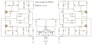
The WMF file attached is the balanced circuit as built, using 4x Toshiba MOSFETs :
http://www.diyaudio.com/forums/showthread.php?postid=1538835#post1538835
One way to see full details is to import the wmf file into Word or Powerpoint.
Patrick
Disclaimer :
Not checked or approved by the original creator of the circuit.
Build at own risk.
http://www.diyaudio.com/forums/showthread.php?postid=1538835#post1538835
One way to see full details is to import the wmf file into Word or Powerpoint.
Patrick
Disclaimer :
Not checked or approved by the original creator of the circuit.
Build at own risk.
Attachments
Hi Patrick, can you please post a schematics in higher resolution - it's not clear where the connections are (cross point in JFETs source resistors) and component values are unvisible ?
jackinnj said:A number of sources (some apocryphal) indicate that the expectation of device failure doubles for every 10 degree C rise in temperature. I saw this quoted in an SMPS textbook a few years back. Other sources say that the adage is somewhat misleading.
This is not far from what I'd consider a fact. In my experience upping the temperature to the specified max. (current VS. temp.) makes the thingie go south within roughly 1000hrs.
> can you please post a schematics in higher resolution - it's not clear where the connections are (cross point in JFETs source resistors) and component values are unvisible ?
It is a Windows Metafile and not JPEG.
The resolution is only poor if you open it with a photo editor sort of program.
What you could do is save it first. Open a new Word document (A3 Landscape), "insert graphics from file", then you will see all details in the highest resolution you might ever need.
Regards,
Patrick
- Home
- Amplifiers
- Pass Labs
- F5 power amplifier