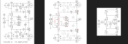
Just a bit of confusion that's all. Too many amps are called F5 hehehe, I'm getting advice from several camps.I want to make sure my poor understanding.
Attachments
Anyone used one of the ps boards intended for the F5m with one of these yet?
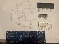
Look at that sassy thing, just mocked up for now because in my infinite goofballery, forgot to order the 2 thermistors, lol.

Look at that sassy thing, just mocked up for now because in my infinite goofballery, forgot to order the 2 thermistors, lol.
I have some to-220 heatsinks that will fit on the front side that I was considering using.Grab a few fender washers for those MOSFET’s next time you’re at the hardware store.
Sure, the idea being to spread the force more evenly across the transistor and not put too much stress on one point...mission accomplished.
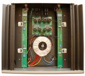
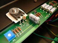
I was looking back at Jim's build guide and came across the photo posted below:
Your standoffs are quite a bit taller than his and I'm hoping the leads on the thermistors you ordered are long enough to bend up over those transistor legs and down to the transistor body. Also, Isn't it standard practice now to have the thermistor touch the plastic casing rather than the washer? Obviously it worked for Jim but I was told not to do it that way. I guess the reasoning would be if the coating on the thermistor were chipped it would make electrical contact with the washer.
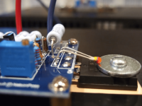

If I have to, I will solder it from underneath and heatshrink the legs and run them through the fet legs.Your standoffs are quite a bit taller than his and I'm hoping the leads on the thermistors you ordered are long enough to bend up over those transistor legs and down to the transistor body.
From the original article:
Th1 and Th2 are small 4.7 Kohm thermistors that have been placed in series with R15 and R16 respectively. The resistance of the thermistor declines with temperature, and if placed in close proximity to the output transistors will help compensate for thermal drift. You can build the amplifier without them, but you will have a longer warm-up time and you will spend more time adjusting the bias.
Th1 and Th2 are small 4.7 Kohm thermistors that have been placed in series with R15 and R16 respectively. The resistance of the thermistor declines with temperature, and if placed in close proximity to the output transistors will help compensate for thermal drift. You can build the amplifier without them, but you will have a longer warm-up time and you will spend more time adjusting the bias.
I've serviced a lot of amplifiers over the years. Vitually all of them have some sort of thermal compensation device mounted on the heatsink. I don't think it matters much if there's a good themal interface.
I imagine not, it just has to change based on temperature and remain consistent if we're trimming the bias with pots anyway.I don't think it matters much if there's a good themal interface.
One more working F5 on the books!
Firm handshakes all around.

Firm handshakes all around.
Not enough open loop gain with such high idss.
The drain resistor value will be lower than expected by the configuration.
Thus, lower level of CLG, or lower feedback for a different sound.
The drain resistor value will be lower than expected by the configuration.
Thus, lower level of CLG, or lower feedback for a different sound.
I gathered items.
I saw EUVL's degeneration jfet matching. 2sk170/2sj74 7.0mA/7.8mA
Matched 2sk1530/2sj201
0.22ohm source resistors and 50ohm feedback resistors.
I would like to have check the schematic and value.
I saw EUVL's degeneration jfet matching. 2sk170/2sj74 7.0mA/7.8mA
Matched 2sk1530/2sj201
0.22ohm source resistors and 50ohm feedback resistors.
I would like to have check the schematic and value.
Attachments
I built the original gb f5 around 2011 or so and I’ve been running it with an aikido 24v preamp. Due to a move I’m reconsidering my listening room layout which would result in my preamp and sources being pit in a rack on the side wall rather than between the speakers.
Interconnect length between pre and f5 would be 4 meters or so, hence considering going for xlr. What would it take to modify my f5?
Interconnect length between pre and f5 would be 4 meters or so, hence considering going for xlr. What would it take to modify my f5?
That is no problem for single ended interconnecting. Imho no need to get through the trouble of switching to balanced interconnects.Interconnect length between pre and f5 would be 4 meters or so, hence considering going for xlr.
- Home
- Amplifiers
- Pass Labs
- F5 power amplifier
