Hello,
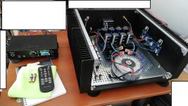
Shift PS-pcb 1cm to front, bias new, add cap RCA input GND, and now it ist running very well.
Seems it is now more transparent and faster as my old F5 with unselected parts prototyp with laterals....
I noticed also that the mids and highs have more texture....
my favorit song now is...
Gregory Porter - Eeverything you touch is gold
==> you = Nelson Pass 😀
thanks to all supporters.
Attachments
Hi
about oscillation:
is my statement correct if i write that the F5 is critical without a "safety" cap at the RCA inputs? I see that the F5 is a pure DC amplifier without caps. in the document its "just" written that it might be an oscillation issue.
Why is no cap like Harry did it in the schematic?
chris
F5 is good as prescribed
no more critical to build and function, if you go by the book
F5T is tricky, in most cases not exactly for novice
no more critical to build and function, if you go by the book
F5T is tricky, in most cases not exactly for novice
Thank you Zen Mod for your answer.
I am thinking about that because if you leave the amp without input , e.g. DAC or preamp, for warm up the F5 during you are listening to another amp.
is then the possibility that the F5 get oscillating and then burn like Harry had?
I am thinking about that because if you leave the amp without input , e.g. DAC or preamp, for warm up the F5 during you are listening to another amp.
is then the possibility that the F5 get oscillating and then burn like Harry had?
if built properly, no problem
though, good practice is to close input in circumstances as that.... with tube amps you must also connect load on output
though, good practice is to close input in circumstances as that.... with tube amps you must also connect load on output
if you leave the amp without input , e.g. DAC or preamp, for warm up the F5 during you are listening to another amp.
I think it's worth saying that if you do this
You MUST switch off the amp before plugging anything into it!
Hot switching is a bad idea.
yes i know that.
so before connecting you should switch off or load the amp but if you warm up the F5 during you listen to another amp and you do not have this input 1nF caps then it might be that you get oscillation?
so before connecting you should switch off or load the amp but if you warm up the F5 during you listen to another amp and you do not have this input 1nF caps then it might be that you get oscillation?
Don't forget that the F5 is a wideband amplifier that goes up >500 KHz.
This from the F5 manual at First Watt:
A caveat is in order here – this is a very wide band amplifier with a high input
impedance. In order to prevent the output voltage from bleeding back to the
input at very high frequencies (thus making a fine power oscillator), keep the
input and output cables separate, and don’t externally connect the speaker
ground to the input ground. Good ground shielding on the input cables is
important, and caution is called for in using Litz and other specially low
inductance / high capacitance cables. I have not seen a specific example of a
problem, but historically it is to be expected when an amplifier’s bandwidth
exceeds 200 KHz. If the amp makes funny noises, runs extra hot, or blows
fuses, this might be an indicator of such an issue.
Harry, your sig in & spk out leads are very close to each other.
Andy
Hi
about oscillation:
is my statement correct if i write that the F5 is critical without a "safety" cap at the RCA inputs? I see that the F5 is a pure DC amplifier without caps. in the document its "just" written that it might be an oscillation issue.
Why is no cap like Harry did it in the schematic?
chris
I'd say that "safety" cap you refer to at the input is not a DC blocking cap.
It connects from the hot/signal input directly to ground. What it does is
shunt RFI to ground keeping it out of the amp. The amp is still a DC amp.
ICHI
hi guys
thank you for your answers. my idea was if i lend this amp to my friends what should be important. thanks to Awh to point this important section of the amp !
thx
chris
thank you for your answers. my idea was if i lend this amp to my friends what should be important. thanks to Awh to point this important section of the amp !
thx
chris
Hey,
for me it was a useful habit to warm up the first prototype, with laterals and no selected parts, with open input RCA´s.
The new F5 as a difference: has selelcted part, an input AC filter 6A (Schaffner) and for internal cabling of the RCA input RG159/50ohm coax wire.
Transformer and Powersupply are equal...
so I guess ,as the new ONE is sounding better, it is more sensitive, cause the IRFP-MosFET are different in high frequency feedback and sounding characteristics??
I do not criticize the F5 circuit and the devolpment....😉
I can live with the feature, that on this F5 there has to be no open input if it is ON
regards Harry
Ivé sold my F5 amp and before the buyer picks it up he wants me to check the bias.
And I´ve forgotten how to.
Any on have any links to setting the bias?
Or can explain to me?
And I´ve forgotten how to.
Any on have any links to setting the bias?
Or can explain to me?
Setting the bias on an F5 is a never ending story one pot raises the voltage and the other one lowers the voltage .....
Hello everyone,
for about 2 months the F5 clone has been driving my Audiovectors, the sound is really good, clean without a hum.
I want to improve the parameters of my amplifier. Currently, I have a quiescent current of about 1.75A and a THD distortion of 0.017%, dynamics 90.3dB, noise 97.2dB.
I would like to improve the THD and noise level in my F5. I know this amp can have a THD of 0.002-0.005% and some examples 0.001.
I plan to increase the quiescent current to 2A, but I have to improve the cooling (1.75A and heat sink temperature 57 degrees C), maybe some fans.
Here's a question for you, what do I have to do to get THD below 0.005%.
A photo of my F5
An externally hosted image should be here but it was not working when we last tested it.
Monoblocks would be a real improvement. Otherwise match all the parts, and use low inductance source resistors.
Also use five series 10R feedback resistors (the exact same part as the 10R to ground), to cancel distortion
due to thermal modulation. That means a new board layout.
Also use five series 10R feedback resistors (the exact same part as the 10R to ground), to cancel distortion
due to thermal modulation. That means a new board layout.
Last edited:
Thanks rayma for replying to my post. My amplifier is dual mono. I tried to add a photo but something does not work.
The source resistors I used are Arcol HS25 R47 1% if they will be good. you can write something more about these 10R resistors, which they have number in the diagram
The source resistors I used are Arcol HS25 R47 1% if they will be good. you can write something more about these 10R resistors, which they have number in the diagram
An externally hosted image should be here but it was not working when we last tested it.
I looked at the diagram and it is a question of replacing two 100R resistors connected in parallel with five 10R connected in series. Will 5W resistors be appropriate or would I have to use 10W?
Why does such a series connection of resistors have a better effect on THD?
I have one more question, maybe a lot of these questions at once, but with one tampering with the amplifier I would like to correct the weak points of my F5.
How can I improve the dynamic range of my amplifier?
Why does such a series connection of resistors have a better effect on THD?
I have one more question, maybe a lot of these questions at once, but with one tampering with the amplifier I would like to correct the weak points of my F5.
How can I improve the dynamic range of my amplifier?
Last edited:
Calculate the power dissipation in the feedback resistor at full power (roughly 5W), and derate each of the series 10R accordingly. For example, each of the series 10R would dissipate roughly 1W, so derate by a factor of three to ten, depending on the parts and board space available. Use the same part for the 10R to ground. But use the very best
quality resistors for the feedback network, since it determines the performance of even an otherwise perfect amplifier.
This works because all six of the feedback resistors have the same signal on them, and present the same error
(mostly thermal modulation distortion), but this is cancelled out when scaling the output voltage down to
that across only one of the six resistors. All behave the same (if in the same thermal environment), so to a
first order approximation, the error drops out of the equation.
Dynamic range would have to extended either downward by lowering noise, or upward (in current)
by adding additional parallel output devices. Some remove the current limiting circuit, but with added risk.
Also look into adding snubbers to the secondary transformer windings.
Last edited:
- Home
- Amplifiers
- Pass Labs
- F5 power amplifier