Hi as I not too sure on how to use this site to look up article s ,, I've jumped in on this f5 discussion hope you don't mind ! I am building a standard f5 and I need confirmation on irfp240 and irfp9240 transistor s ! Do they need to be matched ? As seeing conflicting advice thank you !
You can't easily match N and P parts for Vgs and even if you did, the transfer functions are different. Just use them anyway you want, the adjustment will set up each device to its optimum bias point if you follow the instructions properly.
Matching is for same polarity devices in parallel, so that they share current equally. With the single device per polarity, it is not needed. There is some merit to hitting the right spot with the JFETs, but an exact match is not needed. The inclusion of P3 takes care of most of the mismatch anyway.
Matching is for same polarity devices in parallel, so that they share current equally. With the single device per polarity, it is not needed. There is some merit to hitting the right spot with the JFETs, but an exact match is not needed. The inclusion of P3 takes care of most of the mismatch anyway.
F5 distortion
tomas74,
On a lark I measured the distortion of my DIY F5. The measurements
were done using an HP8903. With about 30 min warm up, at 1W into
8 ohms (~2.83V RMS output) I got 0.0036% and 0.0044% on the
two channels.
The build is pretty standard with Panasonic 0.47 ohm source
resistors and Vishay-Dale for the low power ones. The input jfets
are Toshibas (can't remember the Idss, but likely between 7mA to 9mA).
The outputs are the original Fairchilds. Bias currrent ~1.3A (0.6V across
0.47R source resistors) P3 was left at mid point so no trimming with it
was done.
I found an old post (#1465) where Papa mentioned trimming the distortion
by adjusting the source resistors:
https://www.diyaudio.com/forums/pass-labs/121228-f5-power-amplifier-147.html#post1568027
You must have some nice test equipment and connections. I can’t get that low in distortion testing my test equipment.
Edit:
I lied...just measured Akitika sine wave generator with Keithley 2015 and can get as low as .002
Edit:
I lied...just measured Akitika sine wave generator with Keithley 2015 and can get as low as .002
Last edited:
A diyer friend did some measurements and found his Akitika generator to be
quieter than the HP.
quieter than the HP.
A few days ago I started to change the 10R resistors in the JFet power supply, initially one channel and soldered 15 R and THD from 0.022% to 0.011.
I noticed the right trend, so I soldered 19.6R (two parallel 39.2R) and after adjusting P3 THD went down to 0.0065, it is much better when it comes to parameters. From what I have noticed, when connecting to the sound card (Creative Sound Blaster THX), increasing the resistance value caused the signal to be attenuated by about 3.5 dB.
Maybe it would be different on a different sound card.
I do not know if it was the right step, maybe you can comment on it.
Dennis Hui, what does your power supply look like, standard CRC or something else, what kind of C chip do you have and what capacity?
Last edited:
Hello Gentlemen,
I plan to build an F5 on basis of 4U Deluxe Alu Chassis and V3 boards from DIYaudiostore.
First of all I wanted to read the whole thread, but it seems a losing game with over 1600 pages. So I need your help and advice.
My intention has some modifications of the standard project.
I want to use a soft-start and speaker DC protect board. Why this? I don't like hot running thermistors in a case. I remember all these old tube TV sets with thermistors used then for soft-start.
Nevertheless it couldn't avoid filaments breakdown, especially on weekends and Xmas, when you were watching something interessted.😉
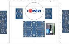
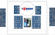
The question is: how to place transformer, power supply and my soft-start boards on the baseplate 360 x 300 mm, so that:
- connections are minimized
- no hum, no oscillation will be detected
- best grounding
My soft-start board is 86 x 66 mm.
I don't want to use risers, there is enough place on the baseplate, I think.
The attached pics showed two possible configurations. Which is better? I apperciate any advice.
I plan to build an F5 on basis of 4U Deluxe Alu Chassis and V3 boards from DIYaudiostore.
First of all I wanted to read the whole thread, but it seems a losing game with over 1600 pages. So I need your help and advice.
My intention has some modifications of the standard project.
I want to use a soft-start and speaker DC protect board. Why this? I don't like hot running thermistors in a case. I remember all these old tube TV sets with thermistors used then for soft-start.
Nevertheless it couldn't avoid filaments breakdown, especially on weekends and Xmas, when you were watching something interessted.😉
The question is: how to place transformer, power supply and my soft-start boards on the baseplate 360 x 300 mm, so that:
- connections are minimized
- no hum, no oscillation will be detected
- best grounding
My soft-start board is 86 x 66 mm.
I don't want to use risers, there is enough place on the baseplate, I think.
The attached pics showed two possible configurations. Which is better? I apperciate any advice.
Attachments
Use your first option. Don't separate the two halves of the capacitor boards or you may have ground-related hum problems. See 6L6's recommendations at the beginning of the Power Supply thread for bonding these two boards together for minimum resistance.
Thanks for the prompt answer. This was my first thought too, even the visual "super-symmetrie" is somewhat teasing.
Is it necessary to use a thermistor to lift the grounding, when the soft-start is built on relais without any thermistor?
Is it necessary to use a thermistor to lift the grounding, when the soft-start is built on relais without any thermistor?
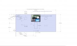
I would go for a third option. Mount the softstart on the back panel and the transformer in the front end of the chassis.
softstart and groundlift are two different things even if they use same components.
some ΩΩ between audioground and protectionearth is a good thing.
some ΩΩ between audioground and protectionearth is a good thing.
> With about 30 min warm up, at 1W into 8 ohms (~2.83V RMS output) I got 0.0036% and 0.0044% on the two channels.
0.0036% is -89dB, which is as low as you get without H2 cancellation.
With perfect H2 cancellation, as in F5X by matching, you can go down to -110dB which is largely H3.
F5X -- the EUVL Approach - The Build Thread
Patrick
0.0036% is -89dB, which is as low as you get without H2 cancellation.
With perfect H2 cancellation, as in F5X by matching, you can go down to -110dB which is largely H3.
F5X -- the EUVL Approach - The Build Thread
Patrick
I would go for a third option. Mount the softstart on the back panel and the transformer in the front end of the chassis.
AudioSan, it is an excellent idea, thank you. Take a look at the attachement.
This is what I have been looking for.
But there is a little doubt: could the small transformator on this board (2.5 VA) stray on the input RCA connectors?
Attachments
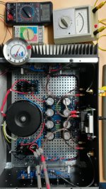
Sorry for being absent so long time, but it took many days to assembly my F5.
Now I'm cooking the left channel, see the picture.
The multimeter measuring the offset is older than most of you, I think. Full range scale is 30 mV.
You could try to guess how old is it...🙂
Now I'm cooking the left channel, see the picture.
The multimeter measuring the offset is older than most of you, I think. Full range scale is 30 mV.
You could try to guess how old is it...🙂
Attachments
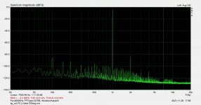
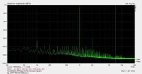
F5 THD+N
My new F5 was ready for some tests, I have done recently.
The figures show distortion at about 1 W for the left and right channels.
You can see the noise floor of 50 Hz harmonics less than -100 dB relative to 1 W power
at dummy load 8 ohm.
The results are a little worser than the original showed in F5 manual.
Do you find it good or bad?😱 I would like to hear your opinion 🙂
Attachments
- Home
- Amplifiers
- Pass Labs
- F5 power amplifier