There are several photos and some text describing the layout I used.
An illustrated guide to building an F5
Here is a link to a PDF with another approach.
An illustrated guide to building an F5
Here is a link to a PDF with another approach.
Hi, another F5 smoker here.
Today I tried to set up bias on my cascoded and doubled output F5. Tried first only one channel with a bulb and everything went fine. Once I pluged amp without bulb and tried to set up bias, one of the P fets warmed dramaticaly more than others. Measured values (P pair only) on 0.47R were 0.1V and 0.15V.
What a difference! Desoldered and checked both P irfp's matching again, fine! Both IRFP9240's have same value!
So I put fet's back and tried to set up bias again, this time a little more open. It took maybe two or three seconds and resistors 47 ohm R13, R113 fired!
I am using boards, schematics and pats list from this guide by Steve and Matt:
https://docs.google.com/file/d/0BzSXoTifUddcNU5TWmpTbm4xYkk/edit
Any similar experiences? what could be the reasons for that behavior?
Thanks in advance for any help.
Jernej
Last edited:
If the gate resistors burned and smoked, something is oscillating. When you replace the gate resistors, use a higher value - 470-680ohm. That will help with oscillations.
Also check your feedback loop.
Also check your feedback loop.
Jer,
did you have open output and shorted input?
That is the correct way to set up your bias current and output offset.
did you have open output and shorted input?
That is the correct way to set up your bias current and output offset.
Yes the gate resistors fired. I'll put some higher value, as suggested.
These four resistors in the feedback loop are 200R instead 100R, so some less feedback and more gain. Maybe this is the reason for an oscillation.
Output is open and input shorted.
I'll continue investigating today evening.
Cheers, Jernej
These four resistors in the feedback loop are 200R instead 100R, so some less feedback and more gain. Maybe this is the reason for an oscillation.
Output is open and input shorted.
I'll continue investigating today evening.
Cheers, Jernej
Yes the gate resistors fired. I'll put some higher value, as suggested.
These four resistors in the feedback loop are 200R instead 100R, so some less feedback and more gain. Maybe this is the reason for an oscillation.
Output is open and input shorted.
I'll continue investigating today evening.
Cheers, Jernej
At least in theory, the AMP gets more stable with lower feedback. So decreasing the feedback is not the way to solve the Problem with the oscillations.
Try increasing the gate Rs instead.
Regards
Flo
Yes the gate resistors fired. I'll put some higher value, as suggested.
These four resistors in the feedback loop are 200R instead 100R, so some less feedback and more gain. Maybe this is the reason for an oscillation.
Output is open and input shorted.
I'll continue investigating today evening.
Cheers, Jernej
I have no idea how folks fry the gate resistors -- if one were to maximize their performance you'd run the amplifier at max out with a square wave and adjust the value of the resistors for symmetry on the positive and negative pulses. Going to a higher value resistor begs instability.
Hi, another F5 smoker here.
Today I tried to set up bias on my cascoded and doubled output F5. Tried first only one channel with a bulb and everything went fine. Once I pluged amp without bulb and tried to set up bias, one of the P fets warmed dramaticaly more than others. ....
One way to read this is that you did not return the pots to zero after unplugging (bypassing) the bulb? Not sure why one would try to set bias and offset with bulb in series, unless it's a sanity check?
The amp won't bias properly with a bulb on the mains, the current draw will light the bulb, keeping the voltage/current low, exactly as it's supposed to.... You can, however, get the pots turned up to a point with the bulb in series that will be much too much when you remove the bulb - but too much bias isn't usually a huge deal, it's just really hot, and easy to turn down.
The smoked gate resistors are proof of oscillation somewhere.
The smoked gate resistors are proof of oscillation somewhere.
I hate to admit it, but my trimmers are mounted backwards. I had forgotten that and had to resort to using the meter to rediscover my error. Everything biased correctly a few days ago, doing everything in reverse.
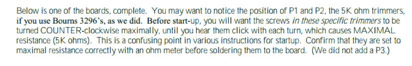
Steve and Matt are wrong, the Bourns click both clockwise and counterclockwise. And they must be zero Ohm initially, and certainly not 5K.
The 'Steve and Matt Document' contradicts initially setting the pots to zero:
Which makes no sense. Max resistance will draw maximum current, and thereby maximum bias.
The 'Jim Document' has a detailed bias procedure - http://www.diyaudio.com/forums/pass-labs/188691-illustrated-guide-building-f5.html
They said that they measured it, but perhaps they were reading something different by measuring in-circuit. ?
The 'Steve and Matt Document' contradicts initially setting the pots to zero:
The F5 manual advised setting the pots to zero for initial adjustment.
Initial Adjustment
Before applying power to the amplifier, you will want to set the values of P1 and P2 to their minimum. Verify this with an ohmmeter. When it comes times to “fire” up the amp first time, if you have a Variac, use it, fusing the AC line to the amplifier with a 1A fast blow fuse. Turn the Variac up slowly, and if you haven’t popped the fuse, then go ahead and confirm the rail voltages to the channels. Each channel does not need to be attached to a load in order to adjust it. If the only load you have is the loudspeaker, I would advise against using it during adjustment. For each channel you will be adjusting P1 and P2 alternately in order to achieve 0 volts DC at the output and .59 volts across R11 and R12. Each time you adjust P1 you will probably have to go back and adjust P2 again, and so I recommend adjusting the pots in half-measures, alternately setting the pots half-way to their voltage goals and measuring the DC values. Unless there is something very wrong, when the output is at 0 V DC, the values across R11 and R12 will be equal.
F5 R1 version tricks and advises
Hello at all! Please a need to ask you what do you think about Aleph
30 vs F5? I have already built my Aleph 30 and I am very satisfied with its
warm sound (similar to a tube), but its ability to control the bass is not its
strong point.
So 'reading around on different forums and needing to use much spare parts of
my old Aleph (dual mono psu, cabinet etc. etc.) I thought that F5 could be ok,
but maybe also aleph X mini monster.
Still reading the forums I learned that P3 pot could minimize distortion .....
but if used skillfully, it could give at the amplifier the right rate of second
harmonic distortion which I think is the peculiarity of the Aleph series.
I still would like to know what does sonically replace R5 R6 R7 R8 100 ohm
with 150 or more.
And finally making a series 50 ohm (fix resistor) +100 ohm (trimmer) + 50 ohms
(resistor fix), can it prevent any damage caused by P3?
Thanks in advance
greeting
Antonio
Last edited:
And finally making a series 50 ohm (fix resistor) +100 ohm (trimmer) + 50 ohms (resistor fix), can it prevent any damage caused by P3?
I am not aware of any damage you can cause by P3. I suppose a very
sensitive driver might be damaged by the small DC offset while you are
making adjustments.....
😎
I am not aware of any damage you can cause by P3. I suppose a very
sensitive driver might be damaged by the small DC offset while you are
making adjustments.....
😎
Hi! Mister Pass ,many pleasure to receive your reply!🙂
The problems were not about the speakers but the stability of the amplifier circuit.
I had to go find him in the depths of the various forums,it was difficult, but not impossible!
#552 post of F5 Turbo Builders Thread
But then translating the various posts I realized that P3 should not have been the problem of Anilva member

But also AndrewT said to Anilva:
Originally Posted by AndrewT View Post
I said a long time ago that the adjustment VR needs fixed resistors either side to limit the extent of adjustment. Seems folk either don't read or have a memory as bad as mine.
So...please can you dissolve my doubts about:
P3 pot could minimize distortion and/or its interaction can generate a predominance of second harmonic distortion as Aleph series?
What does sonically differences replacing R5 R6 R7 R8 100 ohm
to 150 or more?
And finally making a series 50 ohm (fix resistor) +100 ohm (trimmer) + 50 ohms (resistor fix), for P3 is it however a good idea or just a mental masturbation? 😀
Thanks in advance
Last edited:
Originally Posted by AndrewT View Post
I said a long time ago that the adjustment VR needs fixed resistors either side to limit the extent of adjustment. Seems folk either don't read or have a memory as bad as mine.
So...please can you dissolve my doubts about:
P3 pot could minimize distortion and/or its interaction can generate a predominance of second harmonic distortion as Aleph series?
What does sonically differences replacing R5 R6 R7 R8 100 ohm
to 150 or more?
And finally making a series 50 ohm (fix resistor) +100 ohm (trimmer) + 50 ohms (resistor fix), for P3 is it however a good idea or just a mental masturbation? 😀
Thanks in advance
Increasing R5-R8 will reduce feedback, increase gain and "warm" up the sound.
http://www.diyaudio.com/forums/pass-labs/121228-f5-power-amplifier-374.html#post1831285
Regarding P3 vs resistor-trimmer-resistor combination,
in the later it will prevent an accidental shorting to ground if you zero out the trimpot.
Last edited:
F5 heated sound tricks
This is the Papa's Way
Alternatively, you can increase the value of the Source resistors to 1 ohms,
and increase the value of the feedback resistors from 2 X 100 ohms and 10
ohms to 1 X 100 ohms and 22 ohms.
The lower amount of feedback will warm the sound up, and you can keep
increasing proportional values in the feedback loop if you wish.
Same Q:
1)Other tips about eliminating the current limiter?
2)So how to properly adjust P3?
3)What resistors would be preferred in this project?
4 With 1 ohm Source resistor the accross voltage schould be 1.3V or more compatibly with heatsink dissipation?
5) If i reduce to 100 ohm and increase to 22 ohm the feedback network the respective powers will be 5w(or more) for 100 value and 2w for 22 value?
6) About input partitor which values 1k-100k or 4.75k-47.5k?
Many thanks
Antonio
Last edited:
- Home
- Amplifiers
- Pass Labs
- F5 power amplifier