
Never dreamed you would find
Good golly, you never heard of input, output, amplified and/or liquid sound, nor solid state/stage food ?
You do know your gastro-intestinal system has a 3-stage Hung & Chain Lin topology ?
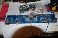
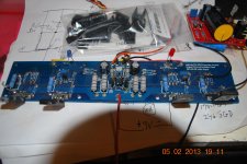
Hi There! I have some questions? On the output of my F5 I got 15mv and when I turn the pots they will climb in mv, but when I stop turning the bias will go back to 0.00mv. The mosfets are frozen. So what did I wrong. Did I positioned Q5 and Q6 wrong (BC560 and BC550) maybe? Thanks for the answer, Teake
Hi intense-tavda,
Post a picture of the board and the schematic used and somebody can tell you what is not working,
Regards,
NS
Post a picture of the board and the schematic used and somebody can tell you what is not working,
Regards,
NS
one of the earlier cviller F5 boards did have a small error around one BC/ZTX 'conversion'
I think the board was correct, but lettering was wrong
don't know if yours is that one
best to look at spec sheets and cross reference with schematic
for some it might be too much to ask
but it's really not that difficult
I recommend to try
I think the board was correct, but lettering was wrong
don't know if yours is that one
best to look at spec sheets and cross reference with schematic
for some it might be too much to ask
but it's really not that difficult
I recommend to try
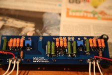
f5 finished. Thanks to everyone whom gave ideas on F5 problem last month. I changed transistors and it works perfectly.
Many thanks to Nelson for this very nice design, have to say sounds fabulous.
Many thanks to Nelson for this very nice design, have to say sounds fabulous.
Hi There!
Teake,
your trimpots fell on their back

I'd check their solder joints, iiwy.
Attachments
Last edited:
Intense-Tavda,
I know those boards all made about the same,so orientation is the same ,You can also pull those trans and measure where the supply voltage pin is then you will know for sure how they go,I hope I have helped some,Good luck!
NS
I know those boards all made about the same,so orientation is the same ,You can also pull those trans and measure where the supply voltage pin is then you will know for sure how they go,I hope I have helped some,Good luck!
NS
Walter -
Nice work, by the way - neat wiring, good layout, I'm looking forward to seeing more photos of your amp! 🙂
Hi 6L6, I posted a lot of pictures in the "pictures of the DIY Pass Amplifier" 😀
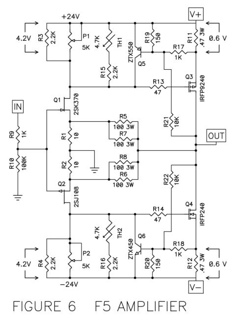
I have two schematics for the regular old F5, with several differing resistor values. One was from Nelson's original guide, and the second from the DIYAudio board guide. Can somebody explain the evolution please, and which I should follow. I am not an EE, so I can't do better than to follow the best prevailing advice. Thanks
R9 is either 1K or 4.75K
R10 is either 100K or 47.5K
R19 & R20 are either 150R or 100R
R13 & R14 are either 47R or 100R
Were these accepted improvements, or what?
Thanks
R10 is either 100K or 47.5K
R19 & R20 are either 150R or 100R
R13 & R14 are either 47R or 100R
Were these accepted improvements, or what?
Thanks
Lucas - are you planning on using a PCB? Which one?
The values from the original Nelson Pass schematic work very well.
The values from the original Nelson Pass schematic work very well.
Last edited:
Well, I have actually populated 2x Peter Daniels boards, but was never happy with them, as I find them far too small and the traces uncomfortably close, not to mention the close spread of the mosfets meaning I will have to extend the connectors, which is not ideal for me and made me feel uncomfortable about it, so I ordered some DIYAudio boards v2. They look much better for me. I was just about to purchase a new set of resistors, when I noticed the differences on the DIYAudio V2 boards build guide, and I see no reference as to why it was changed or indeed who changed the values.
regarding those values - mix them as you want
you'll not hear , or measure difference ( except on very clipping , for R19&R20 , where 100R is value for slightly higher max allowed current )
you'll not hear , or measure difference ( except on very clipping , for R19&R20 , where 100R is value for slightly higher max allowed current )
- Home
- Amplifiers
- Pass Labs
- F5 power amplifier