Hopefully overall gain isn't too low... The F5 can lead to some system gain conundrums if you are using a buffer preamp or a passive...
Hello,
I know that the subject of speaker protection was raised, but i have some questions as I'm considering a relay based dc-protection circuit.
1. What are the chances of getting dc on the outputs?
2. Would relay contacts degrade the sound?
I have expensive and discontinued speakers and don't want to take chances with them.
Thanks
I have beeing using My F5 for months now (whitout the current Limiters)
I have speaker protection with NTE7100
Is good for 2 channels and has delay at power up and speaker disconect at power down (no nasty thumps).
The relays are Amplimo with 2 set of contacts designed on purpose for this aplication.
DC at the output depends on how good your build is and on parts not breaking
Loose solder joint failing pots and mosfet shorth whent they fail.
IMO I would not plug aniting I build to my speakers whitout it.
Quote from Amplimo site>
When switching off the loudspeaker the silver contact opens before the tungsten contact.
The silver contact is protected by the tungsten contact, it never switches high currents, so it will not burn in.
The gold-plating prevents oxidizing of the silver contact, so even years later the contact resistance is very low.
Coil voltage 24VDC nominal, at 70°C 20.4V to 33.5V.
The size of the AMPLIMO relay LR(Z) is standard and it has a standard pin pattern, so it fits on the place of many existing relays.
Relays without a leading contact will have oxide on the contacts when switching high currents of several amps. These oxides cause a variable resistance which deteriorate the damping factor. Moreover oxides do not conduct at low voltages and behave in a non-linear way.
This causes large amounts of distortion particulary at low signal levels.
End quote
I have enclosed NTE7100 pdf
various manufacturer use to produce this chip under different names with similar spec Just search web
Attachments
The F5 continues to be more popular than I expected. As a reward to the
faithful, I have completed the F5 Turbo.
The pc boards are on order, and when they arrive I will present it complete.
😎
ps - you can modify existing F5's to make one.
Tanks Papa
Realy the best Crimbo present.
Unless F6 or F7 is still on? (Gready boyz)
Moddable F5-R1
I am thinking of having some PCB's burned for a moddable F5 R1 -- this to take into account the scarcity of J74BL's. With this board, you can parallel J74GR's. I've also put in some pads for the BF862 N-channel device -- which runs a lot hotter Idss than the K170. K170s don't appear to be in short supply, but forthe purposes of symmetry, you can use 2.
Trimmer P3 is on the board. The MOSFET source resistors -- you can use 0.68R Panasonics, or you can parallel resistors to arrive at some better value. The original R7,8 values were 0.47R. You could parallel 1R and 2.7R to come up with 0.73R, etc., etc.
I also mount the JFET source resistors, feedback resistors and MOSFET source resistors toward the sides so that Caddocks can be mounted and heat sinked without the need of complicated rewiring. Boards will be available at cost, plus shipping and the usual PayPal fees.
An externally hosted image should be here but it was not working when we last tested it.
An externally hosted image should be here but it was not working when we last tested it.
Fortuitous timing. I'm in the planning stage of an F5. Maybe I'll hold off a bit an see what the future holds!
Trimmer P3 is on the board.
In addition to using 11R resistors for R4 and R3 (F5 R1 schematic), you might also consider AndrewT's excellent suggestion of putting ~50R resistors on each leg of P3. That to prevent a disaster should someone slip or make a mistake when adjusting P3. Builders could install the resistors, or put in jumpers. Or you could put in pads for them but require a trace to be cut if they are to be installed.
I followed AndrewT's suggestion on the boards I made for myself,
An externally hosted image should be here but it was not working when we last tested it.
Dan
Hopefully overall gain isn't too low... The F5 can lead to some system gain conundrums if you are using a buffer preamp or a passive...
The gain will be higher.
😎
Hi masters
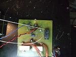
here is my F5 pcb completed,
ı need to construct a box with aluminum.
and ı need a trasformer ı ahve 47,000uf Kendeil caps for PSU.
I'll be apreciate if you recommend
thanx
here is my F5 pcb completed,
ı need to construct a box with aluminum.
and ı need a trasformer ı ahve 47,000uf Kendeil caps for PSU.
I'll be apreciate if you recommend
thanx
An externally hosted image should be here but it was not working when we last tested it.
An externally hosted image should be here but it was not working when we last tested it.
The gain will be higher.
😎
Will anything be sacrificed?

Will anything be sacrificed?
Nothing will be sacrificed.
The F5 will become Shiva, destroyer of small loudspeakers.
😎
Nothing will be sacrificed.
The F5 will become Shiva, destroyer of small loudspeakers.
😎
hey i know your type , going for the most posts in any one thread on an audio forum . you've probably already got guiness book of world records on speed dial 😉

Higher gain sacrifices some bandwidth?
Yes!
Open loop gain (OLG) decreases with increasing frequency, such that the OLG looks a bit like a mountain. Depending on where one cuts this gain mountain, it has more or less bandwidth (as bandwidth is always related relative to voltage gain). Cutting it at high gain (near the top) means smaller bandwidth, cutting it at small voltage gain (near the bottom) means large bandwidth.
Hannes
I have completed the F5 Turbo.
That throws me back to the 90s, with the 'turbo' button and six-digit readouts, that kicked your computer from 66MHz to 100MHz 😱
- Home
- Amplifiers
- Pass Labs
- F5 power amplifier