Re: Re: F5 Pcb
Setting the FET to either side is another possibility that will spread them more, I might do also this iteration which may accommodate some heatsink arrangements.
Regarding ZM comment of temp tracking of the JFET - a valid one regarding offset stability - can be solved by using two small pieces of alu as heatsink a la Cheff DeGaar on his UGS thread. I personally prefer this system rather than cramping both transistors and gain dissipation in the process.
defect9 said:
hmmm... I like it. really simple. curious if the FETs are going to be too close together on the heatsink. maybe swing them out to be on opposite sides of the boards, and make the board a little longer to give them another inch or so. Just my thoughts. Beautiful nonetheless!
Definitely hoping a group buy happens with the final layout, whatever it happens to be.
-Jared
Setting the FET to either side is another possibility that will spread them more, I might do also this iteration which may accommodate some heatsink arrangements.
Regarding ZM comment of temp tracking of the JFET - a valid one regarding offset stability - can be solved by using two small pieces of alu as heatsink a la Cheff DeGaar on his UGS thread. I personally prefer this system rather than cramping both transistors and gain dissipation in the process.
Dougie085 said:Ok well I have 6 of those 6" heatsinks so I could use 2 per monoblock. I'm trying to figure out the easiest way for me to make some PCB's. I found a place that will let you do 3 small boards for like 51 bucks + shipping. Anyone know a better deal? I saw the printer mod for the epson and it looks nice but I think I'd spend more then 51 bucks on that and not sure I'd use it often enough to have a dedicated printer for printing PCB's. Also saw the iron on method with a laser printer but again I'd have to buy a laser printer.
You dont need to buy a laser printer. Local copy shops have laser equipment and will print on your paper(photo paper) Not a big deal.
As for proto boards the best I've used are Velleman sold by All Electronics. Epoxy substrate with your choice of copper patterns. The best part is the flux coating on the copper pads making soldering VERY EASY.
This amp does'nt need a PCB. The biggest expense is the power supply. ZV5 variety will do just fine.
Simplicity triumphs!!
Nelson Pass said:Fortunately, these devices appear to take more abuse than the spec.
I have measured high DG leakage at 42 volts. Of course the 2SK170
and 2SJ74 will take 400 mW, and you can always give them a heat sink.
Noted, thanks.
By the way, some of manufaturers apply low usage fator (=high
safety factor) for their products to buy respected name values,
and minimise any possible claim. Therefore, utilizing the low
usage fator, we could abuse them...
It is the same in the industries where I'm working. But, I always
not allow the users to go over the maximum ratings specified
by the menufaturers, for the safety reason. Watching out and
controlling these kinds of things is my job.
Nevertheless, I have used JFET with more than the rated current
crossing over the Vdg zero axis... 😱
Babowana said:
... the Vdg zero axis... 😱
Sorry...
It has been to be "Vgs" zero axis...
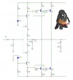
juma said:If we use F5 as a preamp and we loose input buffer from F4 and put them together we might get one serious SuperF amp. My next project:
I do not understand how "your pre" could generate signal
output voltage...

Can you give me a brief explanation...?
Babowana said:
I do not understand how "your pre" could generate signal
output voltage...
Well, the same way the original F5 does, with differences being:
smaller output devices, less Iq, lighter load, bit more CLG, bit less GNFB...

juma said:Well, the same way the original F5 does, with differences being:
smaller output devices, less Iq, lighter load, bit more CLG, bit less GNFB...
Thanks 🙂
So, the load of the pre is R15, R16, R21, and R22.
It's interesting...
Juma
You could get rid of the capacitors C1 and C2 by hooking the bias network between Q1 and Q6 . You might also loose some voltage swing if the front end is not driven with higher rails.
Jam
You could get rid of the capacitors C1 and C2 by hooking the bias network between Q1 and Q6 . You might also loose some voltage swing if the front end is not driven with higher rails.
Jam
jam said:Juma
You could get rid of the capacitors C1 and C2 by hooking the bias network between Q1 and Q6 . You might also loose some voltage swing if the front end is not driven with higher rails.
Jam
I'm not a cap fetishist 😉 This is a low Z (high currents) environment and the influence of the caps is really negligible.
The circuit as it is shown in post #267 can easily swing 22 V which is more than I need. Of course, there are component's values that need tweaking - more about that when it comes to actual building of the amp.
Babowana said:
Thanks 🙂
So, the load of the pre is R15, R16, R21, and R22.
It's interesting...
Yes, and it's not much of a load, right ?
🙂
juma said:Yes, and it's not much of a load, right ?
🙂
Right.
And, it's a "so-called" current feedback...
I hope you will build one prototype...
🙂
Babowana said:
I hope you will build one prototype...
🙂
Me too ! As soon as I find heatsinks big enough and not costing a fortune (Choky might know - he is more into our local scene) 🙂
I'm definitely going to build one of these I'm just not sure which version yet you guys keep posting up all kinds of versions. What does X'd mean exactly? I was interested in the big power version. I want to build 2 mono block amps and I'm thinking 2 of those heatsinks I showed per chassis one per side. Just trying to price everything out and what not. I would like to do a balanced version though but I'm not sure how to design it that way because I'm just not good at that. So if anyone designs a balanced schematic thats finalized let me know I'm very interested 😀 I may just build a BAL to SE converter though for my DAC. It has balanced outputs. I think I'll be starting on this amp before to long though and if I don't see anything else I like better I might just build Nelson's original schematic. The amp is easy I'm still trying to figure out the PSU a bit but I think I got it.
I figured the PSU out to cost about 91 bucks in parts before shipping. About 22 in parts for a single amp board. Does this sound right? I'm not completely sure about the PSU because I wasn't sure what specs the zeeners needed and the rectifiers. Pretty sure those 2MH parts are inductors correct? I couldn't find any 30,000uf caps on Mouser but I found some 33,000 ones. I can look around but I'm pretty sure more is better?
After deciding to jump into an F4 build just prior to Nelson's F5 announcement, I've altered course and I'm setting sail to F5 land. A Zv5 PS is in the works starting later today.
I'm pretty excited.
Thanks for the opportunity,
7/10
I'm pretty excited.
Thanks for the opportunity,
7/10
- Home
- Amplifiers
- Pass Labs
- F5 power amplifier