jimbo51 said:Could it be driven by the standard sizes economically available from the manufacturers of short run pcb's?
Then, I might be suspicious of the manufacturers . . .
As far as I know, R&D departments of famous power amp
manufacturers are doing thermal distribution study too,
in addition to the circuit and sound tests...

> How about scaling the balanced design for more power ?
I assume that you use the same bias (1.3A) on the MOSFETs.
You can then swing a total of 5.2A output current into the speaker. Say you optimise for peak power at 6 ohms. The output voltage is then 31.2V. But you have a bridged amp, so each half sees +/-15.6V max. at any time. There is IMHO no need to go to 35V rails. 24V is plenty.
Appart from that the JFETs won't take 35V, you are also running quite a bit of power into these devices (especially for 2SK370 / 2SJ108 which are specified at some 200mW at 25 degC). Of course you can solve all that by cascoding the input stage.
I have not managed to figure out why you need diodes between the JFET gates ??
Patrick
EUVL said:Apart from that the JFETs won't take 35V, you are also running quite a bit of power into these devices (especially for 2SK370 / 2SJ108 which are specified at some 200mW at 25 degC). Of course you can solve all that by cascoding the input stage.
Fortunately, these devices appear to take more abuse than the spec.
I have measured high DG leakage at 42 volts. Of course the 2SK170
and 2SJ74 will take 400 mW, and you can always give them a heat sink.
It ain't pretty -- gonna go out to dinner while the thermistors get stuck to the output devices:
An externally hosted image should be here but it was not working when we last tested it.
This amp is simple enough makes me want to try out making my first PCB. How big are the heatsinks you guys are using? I'm hoping I can make a relatively small sized chassis for one of these. Maybe 2 mono blocks with these heatsinks I have that are 6" long and almost 6" wide. They are from the guy on ebay that sells them in 12" pieces I had him chop them down to 6" each for the Aleph 30 I never finished.
EUVL said:> How about scaling the balanced design for more power ?
I assume that you use the same bias (1.3A) on the MOSFETs.
You can then swing a total of 5.2A output current into the speaker. Say you optimise for peak power at 6 ohms. The output voltage is then 31.2V. But you have a bridged amp, so each half sees +/-15.6V max. at any time. There is IMHO no need to go to 35V rails. 24V is plenty.
Appart from that the JFETs won't take 35V, you are also running quite a bit of power into these devices (especially for 2SK370 / 2SJ108 which are specified at some 200mW at 25 degC). Of course you can solve all that by cascoding the input stage.
I have not managed to figure out why you need diodes between the JFET gates ??
Patrick
There are several reasons I am using the +/-35V rails. One is that the design is not limited to class A, the circuit will do class B but with increased distortion. Another is I want more output power. Finally I have some huge 750VA 50VAC (single supply) transformers waiting for a design like this.
You are right about the JFET's and cascoding them will fix the problem and I could go back to using the other JFETs. I have also found that adding cascodes will require compensation.
A crazy idea has just come to me, because there is a fixed voltage drop across the JFET then I could possibly use a series zener instead.
Increasing the voltage between the JFET gates increases the JFET bias current, and so the mosfet bias, without continually increasing the JFET drain resistors (which does reduce the amp's bandwith).
Cheers
Tim
Dougie085 said:
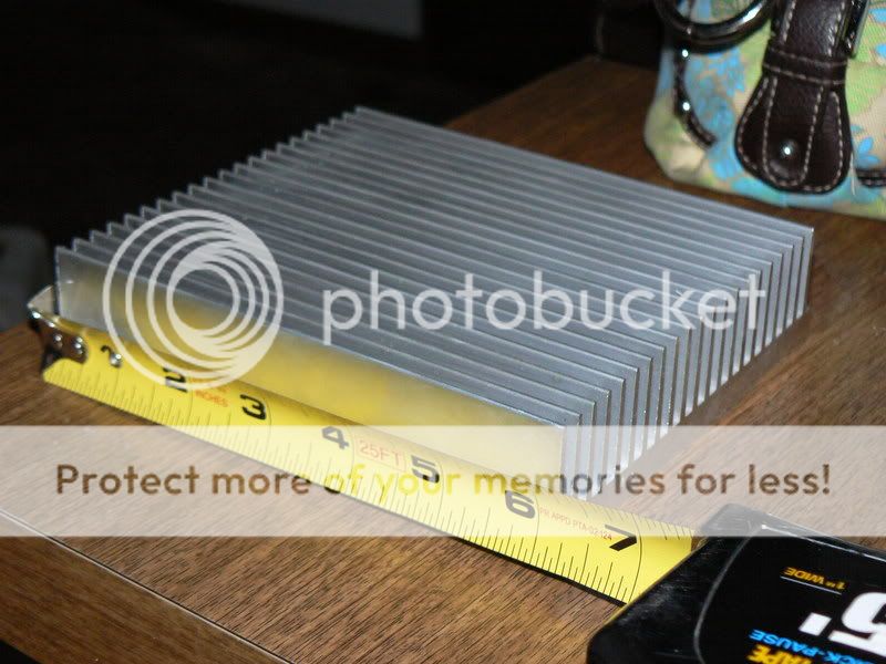
Here is a picture I was just wondering if this would be adequate enough for 1 channel?
Is that your purse in the background? 🙂
I believe that the article said 0.8 C/W --
I'm not big into heatsink specs. The guys says this ".75 c/w per 6 inch section or better" does that mean it should be ok?
And thats the wifes purse 😀
And thats the wifes purse 😀
To get the front end bias back up while keeping the 100R's in the sources, it looks like. Probably not the most elegant solution (wrt impedance, PSRR).EUVL said:I have not managed to figure out why you [TimS in his last proposal] need diodes between the JFET gates ??
- Klaus
So I'd be better off just getting 2 12" long ones? They do .375 c/w. With just 2 fets be hard to put them on 2 different heatsinks I would think. Unless I didn't mount them on the PCB but wouldn't that take away from the sound quality? I've heard some people say they should be on as short of leads as possible.
Woohoo!
My copy of AX has arrived!
Thank you so much, Mr. Pass. (And I wish you
a speedy recovery.)
Dennis
My copy of AX has arrived!
Thank you so much, Mr. Pass. (And I wish you
a speedy recovery.)
Dennis
Dougie085 said:So I'd be better off just getting 2 12" long ones? They do .375 c/w. With just 2 fets be hard to put them on 2 different heatsinks I would think. Unless I didn't mount them on the PCB but wouldn't that take away from the sound quality? I've heard some people say they should be on as short of leads as possible.
No problem. I would just run a few inches of wire either way.
Ok well I have 6 of those 6" heatsinks so I could use 2 per monoblock. I'm trying to figure out the easiest way for me to make some PCB's. I found a place that will let you do 3 small boards for like 51 bucks + shipping. Anyone know a better deal? I saw the printer mod for the epson and it looks nice but I think I'd spend more then 51 bucks on that and not sure I'd use it often enough to have a dedicated printer for printing PCB's. Also saw the iron on method with a laser printer but again I'd have to buy a laser printer.
Dougie085 said:Ok well I have 6 of those 6" heatsinks so I could use 2 per monoblock. I'm trying to figure out the easiest way for me to make some PCB's. I found a place that will let you do 3 small boards for like 51 bucks + shipping. Anyone know a better deal? I saw the printer mod for the epson and it looks nice but I think I'd spend more then 51 bucks on that and not sure I'd use it often enough to have a dedicated printer for printing PCB's. Also saw the iron on method with a laser printer but again I'd have to buy a laser printer.
If you toss the current limiting and temp compensation, there's barely
enough to justify a board. Get some prototype board at Radio Shack.

Re: F5 Pcb
hmmm... I like it. really simple. curious if the FETs are going to be too close together on the heatsink. maybe swing them out to be on opposite sides of the boards, and make the board a little longer to give them another inch or so. Just my thoughts. Beautiful nonetheless!
Definitely hoping a group buy happens with the final layout, whatever it happens to be.
-Jared
apassgear said:Here is one way we could lay a one sided board for the F5 circuit based directly on Nelson’s schematic.
Still on the proofing stage so suggestions, discussion and corrections are welcomed.
Needing components to attach the blue LED that will be added soon so no nastyfor this omission please.
Nelson, thanks for sharing this wonderful amp that I’m sure will transcend time and be regarded as a classic. 😎
hmmm... I like it. really simple. curious if the FETs are going to be too close together on the heatsink. maybe swing them out to be on opposite sides of the boards, and make the board a little longer to give them another inch or so. Just my thoughts. Beautiful nonetheless!
Definitely hoping a group buy happens with the final layout, whatever it happens to be.
-Jared
- Home
- Amplifiers
- Pass Labs
- F5 power amplifier