i wonder which part of your stay? because my brother is working there to the end of this month, hope he have the chance to hand on this pcb for me hand on hand. 🙂
Boards received, thank you. Very nice design.
If possible, for next revision, could you make the P1, P2 holes compatible for both types of trim pots: with inline and triangle lead arrangement.
If possible, for next revision, could you make the P1, P2 holes compatible for both types of trim pots: with inline and triangle lead arrangement.
hi,
few questions:
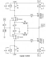
what does the protection circuit protect against exactly?
how much power is dissipated by the mosfet or how do i calculate it( i know that s it s V*I but what else)?
lastly,is this case good enough sinking for the mosfets?
Digi-Key - HM268-ND (Manufacturer - 1444-24)
few questions:
what does the protection circuit protect against exactly?
how much power is dissipated by the mosfet or how do i calculate it( i know that s it s V*I but what else)?
lastly,is this case good enough sinking for the mosfets?
Digi-Key - HM268-ND (Manufacturer - 1444-24)
I have finished to mount the board on the heatsink. I don't use part for the current limiting circuit and the thermistor. Now I have a problem, when biasing I got 4.3 v acros r11 and r12, turning the trim pot don't affect the voltage (is was set a minimum). Any idea what's wrong ?
Thanks
Thanks
The minimized circuit should look like in attached schematic; when all parts are placed properly, it should run fine.
The extra board is for rectifiers, as described here: http://www.diyaudio.com/forums/audio-sector/149672-universal-power-supply-pcb.html
board received 🙂 thanks peter
there is extra ac board which i dun understand what is it for :O
The extra board is for rectifiers, as described here: http://www.diyaudio.com/forums/audio-sector/149672-universal-power-supply-pcb.html
Attachments
I fix the problem. Lucky me, it seem no parts are fried. For now I will test like it with r15 and r16. But why take out r5 and r8 ?
There's no need for additional balanced layout, just run one amp channel with positive phase and the other channel with negative phase of balanced signal as explained here (page 7): http://firstwatt.com/pdf/prod_f4_man.pdf
Anybody still have the original F5 article? Can't find it online anymore and getting close to finishing build and biasing and don't know how? Any help appreciated.
Power supply ground should be connected with Chassis/Earth ground through thermistor as per F4 PS schematic (page 15): http://www.firstwatt.com/downloads/f4_om.pdf
Power supply ground is your main output ground reference and that's why it's tapped off the PS.
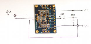
On the amp board you will only see input signal ground with two pads: one to connect ground from RCA socket, the other for a wire to PS ground (reference).
Peter, here's a Jim-Dandy dumb question, but the 2 caps shown here (on your drawing) are the power supply caps, right? ( on your boards ) Making sure there arent two caps I missed somewhere... The ground point between them is the star earth gound? Just making sure before fire up.
I suppose the "jumper" between the power supply board's grounds go to this star as well?
Russellc
Last edited:
Russel,
post452 gives the link to the F5 pdf.
Go to the section headed Power Supply
There is only one paragraph.
You need a PSU for the F5
post452 gives the link to the F5 pdf.
Go to the section headed Power Supply
There is only one paragraph.
You need a PSU for the F5
Russel,
post452 gives the link to the F5 pdf.
Go to the section headed Power Supply
There is only one paragraph.
You need a PSU for the F5
Yes, have that, doesnt answer the question unfortunately. Question concerns Peter's power supply boards.
Russellc
The caps shown in a drawing are on the power supply pcb. The connection between the caps is the power star ground. There is only one wire from amp pcb to that power star ground. The ground from RCA is a signal ground and it connects directly to amp pcb. The power star ground is located on PS board (if you are using one).
Attachments
Peter,
I am trying to work out heatsinks and have two questions.
What is the spacing between the mounting holes when the mosfets are mounted parallel to the pcb (first pic in this thread)? And what would be the distance between them if they were mounted perpendicular to the pcb (as in the way you built you amps)?
thanks
s
The caps shown in a drawing are on the power supply pcb. The connection between the caps is the power star ground. There is only one wire from amp pcb to that power star ground. The ground from RCA is a signal ground and it connects directly to amp pcb. The power star ground is located on PS board (if you are using one).
Thank-you Peter, I thought that was how it hooked up, just wanted to make absolutely certain before calling it done. Thanks!
Russellc
What is the spacing between the mounting holes when the mosfets are mounted parallel to the pcb (first pic in this thread)? And what would be the distance between them if they were mounted perpendicular to the pcb (as in the way you built you amps)?
When mounted parallel, the spacing between mounting holes is 3.6"
When mounted between heatsinks, the required spacing for heatsinks is 3.1-3.2" depending on thickness of isolation pads.
- Status
- Not open for further replies.
- Home
- Group Buys
- F5 pcb group buy...