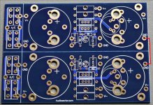
The caps shown in a drawing are on the power supply pcb. The connection between the caps is the power star ground. There is only one wire from amp pcb to that power star ground. The ground from RCA is a signal ground and it connects directly to amp pcb. The power star ground is located on PS board (if you are using one).
Two last questions Peter, where on the power supply board does the wire from the amp pcb connect? Secondly, this star ground must also ground to the chassis?
Thanks,
Russellc
If you are using my PS boards, you need to connect grounds from positive and negative sections together (red jumper in attached pic). This is your power star ground and here you also connect the output ground to the speakers and signal ground wire from amp board.
Chassis connects directly to Earth ground from power entry module, power star ground connects to chassis through CL60 thermistor (as in schematic here, page 18: http://firstwatt.com/pdf/prod_f5_man.pdf )
Chassis connects directly to Earth ground from power entry module, power star ground connects to chassis through CL60 thermistor (as in schematic here, page 18: http://firstwatt.com/pdf/prod_f5_man.pdf )
Attachments
If you are using my PS boards, you need to connect grounds from positive and negative sections together (red jumper in attached pic). This is your power star ground and here you also connect the output ground to the speakers and signal ground wire from amp board.
Chassis connects directly to Earth ground from power entry module, power star ground connects to chassis through CL60 thermistor (as in schematic here, page 18: http://firstwatt.com/pdf/prod_f5_man.pdf )
Whoops, I tied them together, but did so at the pair of grounds next to the pads for c2 and c4. Do I need to move it, or is this OK?
russellc
It's perfectly fine, actually even better.
As to the ground wire from the amp board and the wire going to the negative binding post ( output ) can I attach them at the other ground "holes" on the PS board, or should I strip the jumper and attach them directly?
Sorry if this is too nit picky, I think I'm done now!
Russellc
I don't think there would be a problem connecting them to other pads, although doing it centrally would be more accurate.
Peter, rereading your Power Supply thread, I see I was supposed to use isolation pads under the MUR 3060. Unfortunately, I used transistor grease on them. Hopfully this didnt screw them up. I guess I need to remove the diodes, clean up the grease, and reinstall with silpads?
Thanks again-
Russellc
Thanks again-
Russellc
Caps for PS boards
Hi Peter...
I am contemplating using your PS boards for an F5 mono block build. I was wondering how much, or how little capacitance you suggest? I was thinking of buying some Panasonic TS-UP 50v 18,000uf from Apexjr on the cheap @$2.50 a pop. I know Nelson suggests 120,000 total / 60,000 per channel, so I assume that 72,000 per channel will be enough... or maybe too much? Or should I just consider different caps all together? Just wondering...
With your PS boards I would just pop in the 8 x .47/3watt resistors along with the caps and I would be good to go, right? Can also leave out the thermistors and R9/R10 on Nelsons PS diagram... I think these are used to bleed off power from the caps? Is this correct?
As far as using bridge rectifiers or diodes... I know you have used MUR3060 on some of your builds but those are pretty expensive, what are the real differences in the two? Any other fast diodes you recommend?
Thanks in advance!
erpiii
Hi Peter - just sent you funds for 1xF5 and 2xUniversal PS PCBs. Hope the funds reach you ok, any problems please let me know. Thanks for making this possible.
Justin.
Justin.
Initial fire up of the left channel power supply showed exactly double the voltage, 50 volts DC with 120 volts AC. Shut down, hopefully it didnt harm caps, they didnt do anything funny or get hot...Tried to fire up the right channel, same 50 volts DC, so shut down. This is power supply only, not hooked up to the boards...each channel has its own antek 300 VA transformer.
Obviously I've miss wired something, to be getting exactly double what I'm looking for. I have the Daniels power supply boards as well as diode cards using the MUR 3060 devices. I cant see it, maybe I just need to step away for a while. Any obvious choices where I could have missed wired to cause a double reading?
Thanks in advance,
Russellc
Last edited:
What is the transformer secondaries (voltage, dual or CT)? How did you wire it, any pics?
I havent installed the Thermistors, I was just testing the power supply. I Connected the two red primaries together and the two black ones together. Wired that to a temporary plug, (just one channel at a time) and that plugged into a variac. On the other end, The transformer lines go to a terminal block, from which it goes to the diode boards, then on to the power supply boards.
I'll measure the transformer secondaries and post a pic as soon as my batteries recharge, almost done now.
Russellc
Hi,I havent installed the Thermistors, I was just testing the power supply. I Connected the two red primaries together and the two black ones together. Wired that to a temporary plug, (just one channel at a time) and that plugged into a variac. On the other end, The transformer lines go to a terminal block, from which it goes to the diode boards, then on to the power supply boards.
I'll measure the transformer secondaries and post a pic as soon as my batteries recharge, almost done now.
Russellc
again - to be sure: "How did you wire it, any pics?"

- Status
- Not open for further replies.
- Home
- Group Buys
- F5 pcb group buy...