f5 or f4 board
hello Peter,
I am looking for a stereo board and a ps board.
What do they cost and what dos shipping to the netherlands cost.
regards
John
hello Peter,
I am looking for a stereo board and a ps board.
What do they cost and what dos shipping to the netherlands cost.
regards
John
Shipping is included in a price of the boards.
F5 amp boards info: http://www.diyaudio.com/forums/group-buys/140306-f5-pcb-group-buy.html
PS pcb info: http://www.diyaudio.com/forums/audio-sector/149672-universal-power-supply-pcb.html
F5 amp boards info: http://www.diyaudio.com/forums/group-buys/140306-f5-pcb-group-buy.html
PS pcb info: http://www.diyaudio.com/forums/audio-sector/149672-universal-power-supply-pcb.html
Hello Peter,
I received them last week, they are looking beautyful.
I am scoring the parts here and there and will post the end result.
best regards John
I received them last week, they are looking beautyful.
I am scoring the parts here and there and will post the end result.
best regards John
Hello Peter,
I have received the boards yesterday and as already said, they look beautiful.
Thank You
Philippe
I have received the boards yesterday and as already said, they look beautiful.
Thank You
Philippe
Can anyone suggest a good source for parts (transistors that is). I could not find anything @ digikey or mouser.
Thanks
Thanks
Can anyone suggest a good source for parts (transistors that is). I could not find anything @ digikey or mouser.
Thanks
You should be finding most everything there. That said, I took the easier route of using Tech-Diy parts pack. Jack participates on this board.
Russellc
Note that the Tech-DIY parts kit needs a bit of work to mount properly on Peter's board. The resistors are all mounted vertically and the Ohmites mount to the back of the board. Can take a while to figure out how to mount these on a chassis this way...
Note that the Tech-DIY parts kit needs a bit of work to mount properly on Peter's board. The resistors are all mounted vertically and the Ohmites mount to the back of the board. Can take a while to figure out how to mount these on a chassis this way...
I just used the standard Tech DIY parts and stood the resistors up soldier style.
Russellc
Attachments
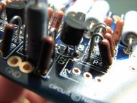
My parts kit was a bit different - I got sent a bunch of Ohmite resistors (which NP mistook in someone else's post as a cap).
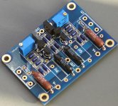
This is my board:
This is my board:
An externally hosted image should be here but it was not working when we last tested it.
The board was designed to be used with Dale CMF50 resistors, available from DigiKey: http://dkc3.digikey.com/PDF/C091/P1890.pdf
For the large ones, use 3W Panasonic metal film, also avaialble from DigiKey: http://dkc3.digikey.com/PDF/B092/P1920.pdf
You may also consider 5W Mills and then use single 50R resistors replacing R5/R7 and R6/R8 parallel combos.
I would also suggest simplified amp circuit, without protection circuitry and thermsitors; it really works nice and according to others sounds better. Since such version uses even less parts, you may also consider Caddocks or Vishays: http://www.audiostereo.pl/zalaczniki/1272620_1.jpg
Attachments

Last edited:
Thanks guys - I ordered Tech-DIY parts and I will see how it goes with them. I might just get smaller resistors from digikey later on.
What is th evalue of gate resistor ?
Hi Peter,
I want to connect the mosfet to the board with extension wire.
2 questions :
1) What is the correct value.of the gate resistor ? You mentioned 220 R but the F5 circuit shows 47 at the positions of R14 and R13.
2) Do i need a certain gauge and 105deg rating wires ?
Thanks
kp93300
Mounting on leads from the outputs is sufficient. There are additional holes for standoff mounting as well, if someone wants to use wires to spread devices further way. It's been confirmed previously that even 12" wire runs shouldn't be a problem, but 220R gate resistors should be mounted directly on devices, not on the board.
The rectifiers are MUR3060
Hi Peter,
I want to connect the mosfet to the board with extension wire.
2 questions :
1) What is the correct value.of the gate resistor ? You mentioned 220 R but the F5 circuit shows 47 at the positions of R14 and R13.
2) Do i need a certain gauge and 105deg rating wires ?
Thanks
kp93300
I was biased by other Pass amps that were using that particular resistor value, with F5 it's certainly 47R for the gates
I would use at least 20ga, preferably teflon.
I would use at least 20ga, preferably teflon.
Member
Joined 2002
Teflon wire is the best for such a beast that produces lots of heat inside 🙂 ( class a amplifiers )
Look up silver teflon wire on ebay, you will come across navship's he sells VERY nice and good quality silver/teflon wire, the stuff i use for my speaker cables.
Look up silver teflon wire on ebay, you will come across navship's he sells VERY nice and good quality silver/teflon wire, the stuff i use for my speaker cables.
hi Peter and jleaman
Thanks for the clarification.
My heat sink is too small and hence the need to use extension wires for the mosfet.
I burnt one set of mosfet already following excessive bias adjustment.? That is why I order another set of boards from you
kp93300
Thanks for the clarification.
My heat sink is too small and hence the need to use extension wires for the mosfet.
I burnt one set of mosfet already following excessive bias adjustment.? That is why I order another set of boards from you
kp93300
Is there a short somewhere?
Hi Peter,
I completed the other channel and hook up via a 100W lightbulb in series in the primary ac supply.
When fired up with the dc current on the board I get a constant bright light bulb. Is this normal ?
I have double check the soldering for shorts and stray wires. I cannot find any
kp93300
Hi Peter,
I completed the other channel and hook up via a 100W lightbulb in series in the primary ac supply.
When fired up with the dc current on the board I get a constant bright light bulb. Is this normal ?
I have double check the soldering for shorts and stray wires. I cannot find any
kp93300
You should be on the secondary side of the transformer, after the bridge rectifiers. Your testing to see if you have DC current through, so the light will only glow if you have AC going through (bad-go back and check wiring).
see this site for further info:
Building a Gainclone chip amp power supply.
see this site for further info:
Building a Gainclone chip amp power supply.
Hi Peter, are your F5 boards still available (need four)?
Have you 3pcs CSA309 at 16.9344 (shiga) to sell as well?
Thanks.
Massimo
Have you 3pcs CSA309 at 16.9344 (shiga) to sell as well?
Thanks.
Massimo
Hi Peter, are your F5 boards still available (need four)?
Have you 3pcs CSA309 at 16.9344 (shiga) to sell as well?
Thanks.
Massimo
Hmm. I could use that crystal as well. Digikey doesn't have any right now.
Hi Peter, are your F5 boards still available (need four)?
Both amp and PS boards are available.
F5 info: http://www.diyaudio.com/forums/group-buys/140306-f5-pcb-group-buy.html
PS boards: http://www.diyaudio.com/forums/audio-sector/149672-universal-power-supply-pcb.html
- Status
- Not open for further replies.
- Home
- Group Buys
- F5 pcb group buy...