The blasphemous method to assure absolute minimum DC offset is the <gasp> dreaded DC servo circuit.
The question is where and how to apply such absurdity - if one was to do that.
Dunno, but maybe the idea I came up with back in post - oops in the F5 thread - I think, to use the current limiting transistor for something else, to control the bias via the thermistor. Which means that it could replace the trimmer pots. Which means it could maybe, perhaps get a voltage back around from a DC servo sensor to set the offset to nil??
But, as I said "that's a different amp"...
😀
_-_-bear
Well, thats exactly what I did. I use bipolars in parallel to R3 and R4, and opamps to control them. I actually reduced the values of R3 and R4 to roughly what the pots would give in parallel with all the other stuff there, and then back up just a little, plus emitter degeneration so the control is really soft. the opamps have a very low corner frequency as you would expect from servos. The whole in a stereo chassis with a wimpy power supply ( too eager to get going, I guess.....).
result: nothing to adjust, I just turn on and a few seconds later the amps are working just fine. the bias stays constant regardless of temperature.
and the sound? tried them with two-way speakers (linearised impedance, air motion transformer) and they sound wonderful, relaxed and very clear highs, very good bass, mid range was also very good but the clean highs were what impressed me most. And, the amp is dead quiet inbetween - it's almost shocking when the music starts again.
I then compared them to the following :
100W "classical" AB MOSFET power amp
30W PPP with 4xEL84 tubes
both on Fostex FE108 (bassreflex), and Quad ESL63
The F5 won hands down in all combination, but what particularly stood out was how this amplifier was able to control the Quads. Finally a good amplifier for these speakers!!! Before, I felt the highs were not good and even considered servicing, now I know everything's fine with the speakers - it was a case of amplificus notfittus ;-)
thank you Nelson for this nice design, I like it a lot! And my next build will be monoblocks with bridged F5s and a better power supply...
sorry for the long post
alfred

 Just lovely!!!!! - Phew! -
Hey Alfred,
If everything turns out ok, I too am thinkning about going bridged. I have some 10 ohm drivers I was thinking about thrying this guy out on and I think the extra voltage might be nice.
Interesting on the servos!
Thanks,
Steve
If everything turns out ok, I too am thinkning about going bridged. I have some 10 ohm drivers I was thinking about thrying this guy out on and I think the extra voltage might be nice.
Interesting on the servos!
Thanks,
Steve
my plan is to double up the input and output transistors including the output source resistors, to have more current available. Guess the feedback divider will have to be adjusted as well, I am working on a new layout where I can add more parallel resistors (similar to what Nelson has been doing in his amplifiers, as per the pictures on 6Moons).
The servo design was a bit tricky, since (at least with the "original" PSU) there is a lot of hum on the supply rails, which the amplifier really doesnt care too much about if it is perfectly symmetrical. But since the output mosfets reference the rails, I had to reference the servos to the rails too..... once I have a clean schematic I will post it.
I recognise this is the "listening experience" thread, so as a last comment - I put the servos to have an amplifier that does not need adjustment, and that's why I made the influence of the servos to be just large enough to control the bias and output offset, but minimise impact on the sonic qualities. Lacking comparison to non/servo F5's, I cannot really say if that worked (guess I need to populate a couple more PCBs and try ;-)
Now, I understand doubling up the outputs (to an extent anyway), but what's with doubling up the inputs? or cascoding them? Is that necessary to be able to drive doubled up outputs?
Alfred: Thanks for the endorsement on driving ESLs! No current limiting, right?The F5 won hands down in all combination, but what particularly stood out was how this amplifier was able to control the Quads. Finally a good amplifier for these speakers!!!
Another diyaudio member brought over his F5 (single output device), and we played it on my ML SL3 (4 Ohm hybrid ESLs), and it played pretty loudly 'without burping' (and I think the preamp gave out before the F5 did). So I'm making a couple of F5's...
I use Toshiba outputs, sound wonderful, and w/o tempco they are very DC stable.
I think they are a bit more detailed than Nationals, while not sounding peaky or rough. They are smooth and refined. I use .47r, but lowered R3 and R4 to 1K to get a little more 'action' out of the 5K pot. They otherwise bias up very quickly.
Any other part changes (in particular: R1 & R2, R5-R8) needed when changing the outputs to Toshibas?
Steve,
Those are the only changes I did, I tried .22R as well as source resistance as well, and appeared to act fine. It also allowed for more flexibility setting current. Sound wise I prefer the caddocks .5's.
Those are the only changes I did, I tried .22R as well as source resistance as well, and appeared to act fine. It also allowed for more flexibility setting current. Sound wise I prefer the caddocks .5's.
I use bipolars in parallel to R3 and R4, and opamps to control them. I actually reduced the values of R3 and R4 to roughly what the pots would give in parallel with all the other stuff there, and then back up just a little, plus emitter degeneration so the control is really soft. the opamps have a very low corner frequency as you would expect from servos.
Very good.
I considered something of the sort, but I got enough whining
from DIYers about the bipolar limiters and thermistors in
exactly the same spots.
😎
Maybe we want some mosfets not bipolars in that adjustment spot? Or even a JFET? Hesener your emitter degen is on the adjustment bipolar?
And, you are using two opamps? One per rail.
How do you keep them from "hunting"?
_-_-bear
And, you are using two opamps? One per rail.
How do you keep them from "hunting"?
_-_-bear
I should imagine that a JFET operated in its linear resistive
region would be the most interesting semi to use there.
😎
region would be the most interesting semi to use there.
😎
Hmmm... I wonder if that would/could then resemble some sort of "adjustable" cascode? But of course we're trying to adjust the operating point of the output, not the gain of the input...
Well, how about a current mirror, where we adjust the adjust side and let the mirror'd side do the adjusting, being once removed from any nasty...
Or, perhaps we reference a mirror from the top and bottom halves in the middle and just slide the centerpoint in order to go the other way of the DC drift...
But that's a different amp? 😀
_-_-bear
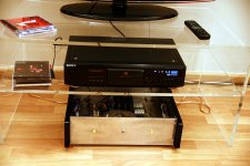
Tonight I connected f5 at 92dB mission m34i speakers - the sound is much more powerfu and dynamic than with my previous 89dB speakers -I keep them for lm3875 gainclone 🙂 . F5 is a very dynamic and nice sounding amp!Some listeners considered that f5 have weak bass, but it seems to me that the bass is very good and fast🙄.
here some pictures of system (very simple - just CD player with line out level control + amp) and some CD`s...
here some pictures of system (very simple - just CD player with line out level control + amp) and some CD`s...
Attachments

Sorry for being offline a little bit - skiing with the family.....
thanks for your comments, I remember in some post in the original F5 thread that Nelson said the (nonlinear) collector cap of the current limiter caps helped to reduce 3rd harmonic, so I basically replaced them with my servo control devices (sorry forgot to mention I don't use the current limiter). I thought about using JFETs, or maybe MOSFETs, but I wanted to change the cap loading of that node as little as possible.
yes, emitter degeneration is at these bipolars. I find that when there is an additional signal inversion in a control loop, with another gain stage, compensating the whole thing gets difficult, since this additional gain (e.g. one transistor) can have a lower bandwidth thanthe main controlling opamp, in which case you're in trouble. degeneration helps to reduce the gain, another option would have been a small cap from collector to base but that would have changed the cap loading at the node I didn't want to touch!
As soon as I can get my hands on a audio analyser I shall be measuring the harmonics, that should give more insight...
as for the two servos: yes it is two opamps (LM2904, nothing fancy), and one is comparing the voltage on the n-channel power MOS with a reference (TL431 + divider), the other one is comparing the output voltage with ground. both have very low corner frequencies. It is important to make them different so they don't oscillate with each other. the "current" servo is at 0.3Hz, I believe, and the "offset" servo is at 0.1Hz (or the other way around - sorry too much sun today!!)
will post a schematic probably next week!
sorry, after rereading another post, I feel I must make one more comment:
I thought a lot about how to servo the amplifier, with lots of complicated current mirrors and such.... but since the original design is of such a simple beauty, there must be a better way. In fact, one servo is only controlling the bias current. By definition, the current must be the same in both halves or you end up with a DC offset..... of which the second servo takes care of, and does nothing else.... so, the second is following the first. If the two halves are symmetrical as good as possible, the resulting bias points will be very close to the trimpot-adjusted F5, in which case the sonic results should be very close as well.
Still have a couple trimpot-F5s, maybe I should do a listening test?
Tonight I connected f5 at 92dB mission m34i speakers - the sound is much more powerfu and dynamic than with my previous 89dB speakers -I keep them for lm3875 gainclone 🙂 . F5 is a very dynamic and nice sounding amp!Some listeners considered that f5 have weak bass, but it seems to me that the bass is very good and fast🙄.
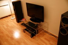
here some pictures of system (very simple - just CD player with line out level control + amp) and some CD`s...
Just a thought-Any reason why you can't bring those speakers out a foot or two? You'll get a much more immerse sound
Hi Hesener,
I'm really looking forward to see your schematics... To me that looks much better than thermal compensation with NTC and unknown DC drift...
What I'm extemely unexperieced:
Compensation of amps. Do you have a good lecture (tutorial) on this???
Regs, Dirk
I'm really looking forward to see your schematics... To me that looks much better than thermal compensation with NTC and unknown DC drift...
What I'm extemely unexperieced:
Compensation of amps. Do you have a good lecture (tutorial) on this???
Regs, Dirk
Hi Hesener,
I'm really looking forward to see your schematics... To me that looks much better than thermal compensation with NTC and unknown DC drift...
What I'm extemely unexperieced:
Compensation of amps. Do you have a good lecture (tutorial) on this???
Regs, Dirk
more effective and easier certainly yes ; funny to implement , yes ; interesting to develop , yes .
better soundwise ....... not so certainly
do not underestimate simple solutions
- Home
- Amplifiers
- Pass Labs
- F5 Listening Impressions & Discussion