adding add-ons is clumsy, probably needs a rejig of entire layout. Still might work satisfactorily well, although ugly looking.
Attachments
Last edited:
Yes, I was already afraid for that. A complete board will result in less wiring and way more easy building but that is no news. Anyway, please think about it. Maybe an integrated power supply is a possibility but that won't come as a surprise coming from me (being a single board maniac) 😉 I don't see the point of wiring with such a small design. Wiring is no fun and a single board will look way more tidy. Just AC connections for the transformer and inputs and outputs.
Last edited:
sorry, cant do, may be someone else could take it up further.😱Yes, I was already afraid for that. A complete board will result in less wiring and way more easy building but that is no news. Anyway, please think about it. Maybe an integrated power supply is a possibility but that won't come as a surprise (being a single board maniac) 😉 I don't see the point of wiring with such a small design. Wiring is no fun and a single board will look way more tidy. Just AC connections and inputs and outputs.
sorry, cant do, may be someone else could take it up further.😱
If someone does decide to take it further (stereo and PSU), here is what I would use, as it has a amenable concept for a central PSU and left and right channels on the left and right of afore said PSU with a nice central star ground. and most importantly, all through-hole things for diy friendliness.
It is also a better layout compared to my earlier layout whose PCB's are being manufactured in China as i write here😱. Cheers to the spirit of DIY!!

reg
Prasi
Attachments

EUVL,when will the pcb´s be ready? 🙂blackdod Spain 2
BMF USA 2
ripson UK 1
hipcheck USA 1
Ryssen Sweden 1
Dennis Hui Canada 1
pchw USA 1
Xen team internal 2
CeeVee Portugal 1
pegasus21 Singapore 1
Fabian85 Germany 1
Running total 14
PCB have been there since April.
The V2 Beta tester has fallen ill, unfortuntely.
If you don't want to wait, we can send yours off.
You know the risk up front.
Or you can also cancel. We don't mind.
Patrick
The V2 Beta tester has fallen ill, unfortuntely.
If you don't want to wait, we can send yours off.
You know the risk up front.
Or you can also cancel. We don't mind.
Patrick
Maybe an integrated power supply is a possibility but that won't come as a surprise coming from me (being a single board maniac) 😉
Just AC connections for the transformer and inputs and outputs.
Nice suggestion about the integrated PS.
What circuit do you recommend for the on-board supply?
PCB have been there since April.
The V2 Beta tester has fallen ill, unfortuntely.
If you don't want to wait, we can send yours off.
You know the risk up front.
Or you can also cancel. We don't mind.
Patrick
Hi Patrick,
Is this the same or better circuit than the one on first post? Can we still buy the PCBs?
Thanks
Do
PCB have been there since April.
The V2 Beta tester has fallen ill, unfortuntely.
If you don't want to wait, we can send yours off.
You know the risk up front.
Or you can also cancel. We don't mind.
Patrick
No I don´t wanna cancel.
There was a thread here at Diyaudio of a F5 head amp building( your pcb),was that the V1?
If you sed me the PCB now I can start with the mecanical konstruktion..
Was he very ill the beta tester?
I´ll send you a P.M about the pcb.
> There was a thread here at Diyaudio of a F5 head amp building( your pcb),was that the V1?
Yes. You can also post your building question there; more tidy.
> If you send me the PCB now I can start with the mecanical konstruktion..
You tell me what dimensions you need I shall send you a drawing.
> Was he very ill the beta tester?
It is his personal information, so I want to be discrete.
But yes, for quite a few months.
Patrick
> Is this the same or better circuit than the one on first post?
Same as V1 with all errors corrected.
> Can we still buy the PCBs ?
You already subscribed for these super bargain PCBs, so why would you want to pay 100x more for ours ? 🙂
Patrick
Same as V1 with all errors corrected.
> Can we still buy the PCBs ?
You already subscribed for these super bargain PCBs, so why would you want to pay 100x more for ours ? 🙂
Patrick
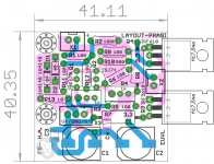
Yes, I was already afraid for that. A complete board will result in less wiring and way more easy building but that is no news. Anyway, please think about it. Maybe an integrated power supply is a possibility but that won't come as a surprise coming from me (being a single board maniac) 😉 I don't see the point of wiring with such a small design. Wiring is no fun and a single board will look way more tidy. Just AC connections for the transformer and inputs and outputs.
Are you looking for something like this? Still managed to fit within 100mm x 41mm. Not too sure about PSU and its caps values. I used a CRC type with 10mm dia caps. Some 2200uF 25V are available in 10mm dia. would they be sufficient? MURS are quite close to each other, may be one could use plastic packs or insulate their backs. A small C shaped aluminium plate could be used as a heatsink for the MURS.
reg
Prasi
Attachments
Last edited:
Prasi,
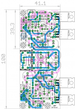
Thanks for your continued efforts. I was worried you had no more time for this but if you are indeed going for an integrated psu - cool. I have tried his amp with just a CRCLC unregulated psu and it doesn't sound good enough as transformer hum gets through. A class A amp without CCS on the input stage had very poor PSRR. So it's up to the PSU to be constant and ripple free. I would suggest adding a independent 7815 and 7819 voltage regulators (or LM317 if you prefer those) with small local heatsinks (or could be mount bent underneath with chassis bottom plate as heatsinks). 4 voltage regulators total and grow size about in the 41mm dimension but keep rectangular format and under 100mm. If you have room, try to make at least 3 stage CRCRC filter with 2200uF 0.22R 2200uF 0.22R 4400uF on output to voltage regulators. The format and compact size you have is great because it could fit in a low cost Breeze case like this one:
http://s.aliexpress.com/QjeueANj
The IRF MOSFETs could be bolted to case side or bottom as well. 3w dissipation per amp channel so not too hot. Fins not needed really.
Finally, if you really want to top it all off, adding the crossfeed filter with volume pot would be a total bonus. All dependent on how much time you feel like putting in.
Thanks,
X
Last edited:
Prasi,
Thanks for your continued efforts. I was worried you had no more time for this but if you are indeed going for an integrated psu - cool. I have tried his amp with just a CRCLC unregulated psu and it doesn't sound good enough as transformer hum gets through. A class A amp without CCS on the input stage had very poor PSRR. So it's up to the PSU to be constant and ripple free. I would suggest adding a independent 7815 and 7819 voltage regulators (or LM317 if you prefer those) with small local heatsinks (or could be mount bent underneath with chassis bottom plate as heatsinks). 4 voltage regulators total and grow size about in the 41mm dimension but keep rectangular format and under 100mm. If you have room, try to make at least 3 stage CRCRC filter with 2200uF 0.22R 2200uF 0.22R 4400uF on output to voltage regulators. The format and compact size you have is great because it could fit in a low cost Breeze case like this one:
1506 E3 Full aluminum headphone amplifier enclosure / case /preamp chassis-in Amplifier from Consumer Electronics on Aliexpress.com | Alibaba Group
The IRF MOSFETs could be bolted to case side or bottom as well. 3w dissipation per amp channel so not too hot. Fins not needed really.
Finally, if you really want to top it all off, adding the crossfeed filter with volume pot would be a total bonus. All dependent on how much time you feel like putting in.
Thanks,
X
Was trading some of my sleep for it. Now its time get my sleep..Thanks for your suggestions. see if you can carry this further with some one else....
reg
Prasi
Last edited:
Spent some time this weekend playing with my p2p f5 headamp. Here's a hint for all of you starting builds: bias, and lots of it is important. Just like it's big brother this amp loves bias current. I wish I had gone with 3 watt source resistors instead of 1 watt. Running 225ma now and it sounds really good. Much fuller and more liquid than at 120ma. I have a lot of heatsink (2107 case) and plan on changing the source resistors to 3 watt and going with 300-400ma bias.
I'd suggest you take the bias as high as your heatsinks, psu and source resistors will let you.
I'd suggest you take the bias as high as your heatsinks, psu and source resistors will let you.
Hi,
What voltage value across the 3.3R for 225ma?
Ohm's Law-----.7425V.
Bias = voltage/resistor value.
.7v across source resistor (3.3 ohm) will give you about 220ma. Problem is with 16V rails and 225ma you dissipate .175 watt through the source resistor. I have watt source resistors and I would like to maintain a 4x (or more) factor for the resistor wattage. I could probably go 300ma (.3W w/3.3R resistor) but I'd rather just put some 2 or 3 watt source resistors in there first. At 225ma the amps heatsonks are not hot (2107 case). Honestly, the regulator mounted on the bottom of the chassis is hotter.
On paper, you don't really need this much bias unless you want to stay in class A with extremely low impedance headphones. But more bias has really given this amp more weight and liquidness which I am liking.
Strange you would use one watt resistors when the initial design called for 2 watt resistors. Unless that's all you had.
- Home
- Amplifiers
- Pass Labs
- F5 Headamp ?