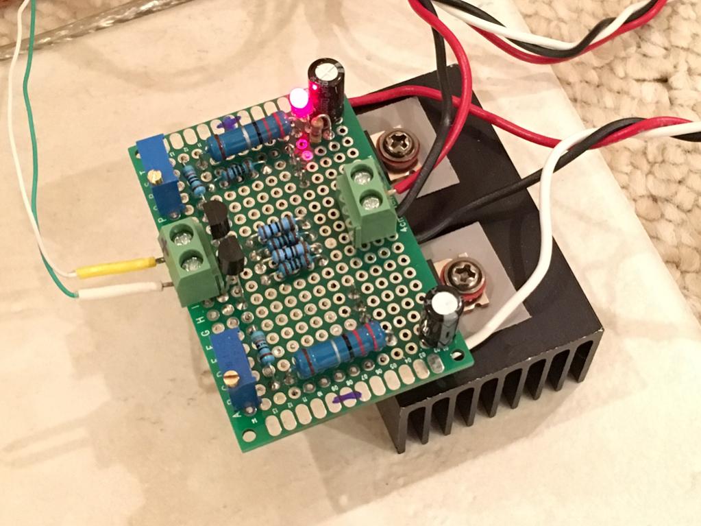
Here is my first attempt with veroboard per the layout in Post #1. I am using 2.2R vs 3.3R source resistors and 10kohm pots as that is what I have on hand. I also added a 47uF 63v smoothing cap and 100nF bypass caps (SMT X7R) on the rails. 100R SMT resistors for the inputs are mounted on the underside. I adjusted the pots for 130mA bias current (290mV over 2.2R) and DC offset is less than 5mV. It's actually driving my 8ohm reference speakers now for testing. The little heatsink came from a cheap class D TDA7498 amp and fits perfectly. It's warm but not hot. What is the correct bias current I should set it at for 15v rails? Also, if I have 21v rails, can that be OK to use as that is one of the toroidal trafos that I have on hand.
Listening to it, it sounds very nice - amazing for how simple the circuit is. I think it's a go for making the second channel for stereo. One thing is for sure, you need a regulated PSU or else you hear hum.
Nice amp, thanks for the design EUVL! 🙂
Listening to it, it sounds very nice - amazing for how simple the circuit is. I think it's a go for making the second channel for stereo. One thing is for sure, you need a regulated PSU or else you hear hum.
Nice amp, thanks for the design EUVL! 🙂
Attachments
Last edited:
21V 130mA is no problem if you use a suitable heatsink (<50°C to ensure low offset) and Kerafol as insulator.
Patrick
Patrick
What bias current do you recommend to stay in pure class A operation? I will be using 60ohm Sony MDRV6 phones - decent sensitivity. Probably not more than 2v needed.
2V / 60ohms = 0.0333A = 33.3mA
Set a push pull ClassA output stage to ~20mA
or set a single ended (ClassA) output stage to ~ 40mA.
Both those options will dissipate very little heat, so I would be tempted to aim for much higher bias, maybe >=100mA
Set a push pull ClassA output stage to ~20mA
or set a single ended (ClassA) output stage to ~ 40mA.
Both those options will dissipate very little heat, so I would be tempted to aim for much higher bias, maybe >=100mA
Last edited:
Ok so my 130mA bias is good then. I can back off a little to keep heat down if I increase rail voltages. Although if I regulate the 21vdc from transformer and caps - probably 18vdc via 7818 and 7918 is good. If hum is still audible add second stage shunt regulator controlled via TLM431 to 15vdc.
Here is my first attempt with veroboard per the layout in Post #1. I am using 2.2R vs 3.3R source resistors and 10kohm pots as that is what I have on hand. I also added a 47uF 63v smoothing cap and 100nF bypass caps (SMT X7R) on the rails. 100R SMT resistors for the inputs are mounted on the underside. I adjusted the pots for 130mA bias current (290mV over 2.2R) and DC offset is less than 5mV. It's actually driving my 8ohm reference speakers now for testing. The little heatsink came from a cheap class D TDA7498 amp and fits perfectly. It's warm but not hot. What is the correct bias current I should set it at for 15v rails? Also, if I have 21v rails, can that be OK to use as that is one of the toroidal trafos that I have on hand.
Listening to it, it sounds very nice - amazing for how simple the circuit is. I think it's a go for making the second channel for stereo. One thing is for sure, you need a regulated PSU or else you hear hum.
Nice amp, thanks for the design EUVL! 🙂
Looking forward to your listening impression
Do
Looking forward to your listening impression
Do
I need to build second unit for stereo, then build regulated PSU for clean power. Then can give it a listen for real. I will compare against JLH head amp which is much more complicated (still simple compared to some amps) BJT class A with quasi-complementary outputs. A few more days for all this to happen though. Initial listening tests with my 8ohm reference speaker sounds very good - for low volume levels equivalent to maybe 1w output. That's quite a bit more than the headphones will ever need.
What is the recommended power supply regulator scheme for this amp? Is it the cap multiplier as suggested way back?
What values need to be different on this schematic to get 15v rails?

Just vary the 12k with a 10k pot?
Thanks.
What values need to be different on this schematic to get 15v rails?
Just vary the 12k with a 10k pot?
Thanks.
I will compare against JLH head amp which is much more complicated (still simple compared to some amps) BJT class A with quasi-complementary outputs.
Hopefully your listening experience of the F5 will be more positive than mine.
Having built and listened to both, there was no doubt which sounded better to me.
My F5 was biased at 150mA and required much larger sinks than you're using.
Offset was quite low after using matched original Toshiba J74/K170s.
After trying it a few days and trying to convince myself that it "should" sound good, I finally removed the JFETs from the boards and threw the rest in the trash.
That does not bode well. I like the sound of my JLH headamp. The JLH, for $20 as a kit is an absolute deal (includes on-board regulated PSU but no trafo). Sometimes more transistors *is* better. I will keep an open mind though.
Hopefully your listening experience of the F5 will be more positive than mine.
Having built and listened to both, there was no doubt which sounded better to me.
My F5 was biased at 150mA and required much larger sinks than you're using.
Offset was quite low after using matched original Toshiba J74/K170s.
After trying it a few days and trying to convince myself that it "should" sound good, I finally removed the JFETs from the boards and threw the rest in the trash.
Can you elaborate a little more? What didn't you like about it?
Can you elaborate a little more? What didn't you like about it?
I answered your PM.
Thanks.
For those who don't have post 137 memorized:

Can't we put a couple of trimmers in this circuit to adjust the output voltages like is typically done with 317/337 supplies?
Would they replace R2 and R7 in the above schematic?
Will 5K trimmers work or should another value be used?
The C-multi on post #608 is the basic one from the Rod Eliot website - the 12k is set for the particular transistors used but a 10kR pot would probably do - maybe add a series resistor if you wanted to be pedantic - more 'up to date' designs use different transistors or power fets - the K-multiplier is a more recent simple design
The one referred to as #137 is essentially the 'TeddyReg' and this, plus a number of variations, can be found on 'PinkFishMedia'
Curiously, they all seem to do a quite good filtering job but they all produce a slightly different sound in similar circuits - and then there's personal preferences ...
The one referred to as #137 is essentially the 'TeddyReg' and this, plus a number of variations, can be found on 'PinkFishMedia'
Curiously, they all seem to do a quite good filtering job but they all produce a slightly different sound in similar circuits - and then there's personal preferences ...
The JLH Class A (Power Amp) was one of my very first DIY projects.
And it is quite nice sounding, which is why it is still being built after so many years.
But since then I have been building FET amps almost exclusively.
I am sure there will be people who prefer the JLH, just like people prefer tube or BJTs to FETs.
Everyone should build what pleases them. There is no univeral best design.
Which is what makes this hobby interesting.
🙂
Patrick
Can't we put a couple of trimmers in this circuit to adjust the output voltages like is typically done with 317/337 supplies?
Would they replace R2 and R7 in the above schematic?
Will 5K trimmers work or should another value be used?
Or maybe 500R trimmers on R1 and R6 as that would land in the middle of the zone as well. I don't have both D45/44H11's on hand so would like to replace with TIP41/42. Will that work ok?
My vote goes to the F5 HA (ranking might be updated in a few days though...) 😉.
Bettered the Dynahi and a few others. But have not built the JLH.
Bettered the Dynahi and a few others. But have not built the JLH.
- Home
- Amplifiers
- Pass Labs
- F5 Headamp ?