I'm building Keantoken's cap multiplier with P2P. Will see if I can get it to work. If not, at minimum will use a 7815/7915 regulator and caps
I thought you already trashed your F5-HA ?
"I finally removed the JFETs from the boards and threw the rest in the trash."
Patrick
Yes, I threw it in the trash months ago.
I didn't say I was going to try a cap multiplier with it.
I'm building Keantoken's cap multiplier with P2P. Will see if I can get it to work. If not, at minimum will use a 7815/7915 regulator and caps
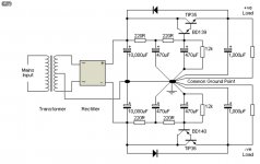
I'm doing a layout for the Elliott circuit below.
At least it's a simple design.
Do you know by chance if 1N4007 diodes will work for the ones in parallel with the TIP's collector and emitter?
Attachments
I'm doing a layout for the Elliott circuit below.
At least it's a simple design.
Do you know by chance if 1N4007 diodes will work for the ones in parallel with the TIP's collector and emitter?
1N4007 is 1000v rated so is the "best" of the 1n400x series so should be fine. I am wondering if I can use TIP41/42?
OK guys, I put my amp through some software-based testing.
A) I barely know what I am doing here...take it easy on me. I have no formal training and all I know is self-taught and learned here. So be nice.
B) The amp was hooked up to an USB audio interface and ran into my macbook. I have no idea of the load placed on the amp or the noise produced by the USB interface.
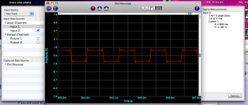
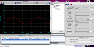
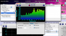
I have tested a sine and square wave, harmonics and octave. Sine looks good, Sqaure looks bad (don't know if I am doing something wrong), harmonics look good. I will attempt a FR response measurement if I can figure out how to do it.
I am I wrong in saying the amp looks fine?
A) I barely know what I am doing here...take it easy on me. I have no formal training and all I know is self-taught and learned here. So be nice.
B) The amp was hooked up to an USB audio interface and ran into my macbook. I have no idea of the load placed on the amp or the noise produced by the USB interface.
I have tested a sine and square wave, harmonics and octave. Sine looks good, Sqaure looks bad (don't know if I am doing something wrong), harmonics look good. I will attempt a FR response measurement if I can figure out how to do it.
I am I wrong in saying the amp looks fine?
Attachments
OK guys, I put my amp through some software-based testing.
A) I barely know what I am doing here...take it easy on me. I have no formal training and all I know is self-taught and learned here. So be nice.
B) The amp was hooked up to an USB audio interface and ran into my macbook. I have no idea of the load placed on the amp or the noise produced by the USB interface.
I have tested a sine and square wave, harmonics and octave. Sine looks good, Sqaure looks bad (don't know if I am doing something wrong), harmonics look good. I will attempt a FR response measurement if I can figure out how to do it.
I am I wrong in saying the amp looks fine?
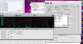
I beat on the computer and got a frequency response. This explains a lot I think.
What do you guys think?
Attachments
1N4007 is 1000v rated so is the "best" of the 1n400x series so should be fine. I am wondering if I can use TIP41/42?
Thanks x.
I thought I read somewhere on this forum about the TIP41/42 causing possible oscillation problems in a PS design.
I've read so many posts that I may be confusing it with something else.
Why don't you post the question over in the "Power Supplies" section?
Or...just add a TIP35 and 36 to your next Mouser or Digikey order.
What do you guys think?
Something is not quite right with your build:
- From the square wave, it seems there are signs of oscillation (you may want to check the output from your signal generator though)
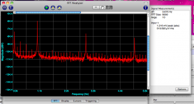
- For the FFT, you may want to use higher magnitude (e.g. -10dBV) for the fundamental, to show more reasonable THD figures. As it showed, the third harmonic is only 20dB below the fundamental.
- The frequency response looks terrible. Compare that with figure 8 of the official build guide.
Your sound card has limited bandwidth and hence you will not be able to generate or measure a proper square wave with it.
The overshoots you see can either be from the amp itself, or from the sound card.
Same problem with the frequency response (not enough bandwidth).
You need a proper oscilloscope.
And the old analog ones normally come with a built-in 1kHz square wave generator.
Many new USB scopes also come with a Func Gen.
Patrick
It's not easy to make a DIY rig to measure amps. Need high quality low noise and low distortion external sound card. Need voltage divider. Need resistive load with heatsink. Can be done with REW software with built in function gen and RTA function. Need to calibrate out the sound card response.
What you should check first with the F5-HA is high frequency oscillations.
This can be way over 1MHz, and you will still get sound.
So having sound is no guarantee.
The proper way to find out is a frequency sweep to 5MHz if possible.
A fast ocillocope with a 100kHz square wave will be minimum to check any overshoot.
If you have a lab power supply with current limit, you might also be able to pick up large oscillations (when it goes wild).
The power FETs and source resistors will also get hot when input is grounded and output is loaded (e.g. 200R).
The load resistor itself will also get hot.
Without any equipment, it is really difficult to tell.
Patrick
Thanks Patrick.
I will construct the cap multiplier section after the 317/337 and try that as well...I have a feeling the reg might be causing problems, I used what I had for the output and bypass caps, they are low esr. Usually not an issue but it might be with this amp.
I'll keep my eye out for a good scope. It is something I should have. Not ready to give up on this amp yet.
Also, for the caps in the cap multiplier section is it ok to increase the value from 330uf to say 2200uf? I have 4 2200uf nichicon fw left over from a previous project.
1) You should not buy a scope for this project alone. You want to buy one for future DIY also.
2) A 2nd hand 1MHz analog scope is not expensive, and better than some cheap USB scopes.
But there are probably better advances at the equipment section of DIYA.
3) You can increase 330uF to 2200uF. Bear in mind the larger the cap, the earlier it becomes inductive.
4) If you use high impedance phones (>200R) with thick capacitive cables, adding a 65R 2W resistor at the output in parallel with the phone will help stability.
Patrick
Last edited:
A Zobel network will also serve the purpose.
But :
1) In all the builds so far tested with a variety of phone, it is not proven necessary.
2) The values of R1 C1 needs optimising with a frequency response sweep.
A simple 65R power resistor is simpler and also does not add additional phase shifts.
The only disadvantage is that it loads the amp more.
But the F5-HA will drive 50R or even less with ease, so no issue.
A Zobel network is, e.g. used in the DAO SE.
Patrick
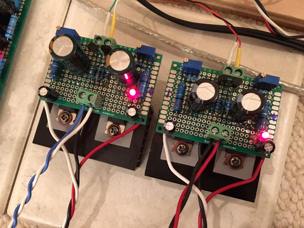
F5 Headamp in Stereo
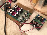
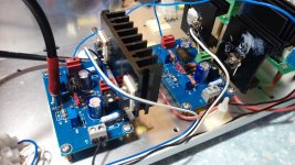
Finally listening to it in stereo. 100mA bias current seems to be a good match for the smaller heatsinks I have on the 7815/7915 and sounds good. The PSU is a CRCLC with 2200uF x 4 total per rail. PSU ripple at amp input is ~1mV. Absolutely silent when no music playing. These are not my good headphones as the MDRV6's are at work, but give me a good idea of the sound quality. So far so good - very clean, highs are very clear, bass is nice and deep. Will take more time later with better headphones before final assessment but like it so far.
It's too loud - maybe need less gain - an input pot? I have the DAC output turned way down to like 4 out of 100.
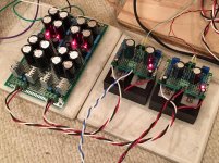
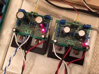
System with PSU, not shown in an Antek 100VA 15VAC toroidal transforner:

Closeup of amps:
PSU:
http://www.diyaudio.com/forums/atta...-f5-headamp-f5-headamp-build-stereo-psu-4.jpg
Finally listening to it in stereo. 100mA bias current seems to be a good match for the smaller heatsinks I have on the 7815/7915 and sounds good. The PSU is a CRCLC with 2200uF x 4 total per rail. PSU ripple at amp input is ~1mV. Absolutely silent when no music playing. These are not my good headphones as the MDRV6's are at work, but give me a good idea of the sound quality. So far so good - very clean, highs are very clear, bass is nice and deep. Will take more time later with better headphones before final assessment but like it so far.
It's too loud - maybe need less gain - an input pot? I have the DAC output turned way down to like 4 out of 100.
System with PSU, not shown in an Antek 100VA 15VAC toroidal transforner:
Closeup of amps:
PSU:
http://www.diyaudio.com/forums/atta...-f5-headamp-f5-headamp-build-stereo-psu-4.jpg
Attachments
Last edited:
It was used with cross feed which reduce the signal by 10dB.
You can just add an input pot.
Congratulations. 🙂
Patrick
You can just add an input pot.
Congratulations. 🙂
Patrick
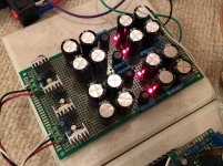
Hi,
I also kind of finished mine today, it was based on Patrick's original schematic and a friend helped to make the PCB, I added a 10K volume port to lower the gain too, no noticable noise heard so far. Mosfet used are IRF610/9610 (didn't match the mosfet), Jfet were matched to 7.65ma, DC was quite low but forgot what exactly the number was. Power supply is just a 7A4700 from a local vendor bought few years back. I am going to try other regulators when have time , get a better case, tidy up all the wiring and work on the cross feed filter. Sound is good at first shot, plenty of base and very detail. This is my first headphone amp built, thanks for providing such a clean design.
I also kind of finished mine today, it was based on Patrick's original schematic and a friend helped to make the PCB, I added a 10K volume port to lower the gain too, no noticable noise heard so far. Mosfet used are IRF610/9610 (didn't match the mosfet), Jfet were matched to 7.65ma, DC was quite low but forgot what exactly the number was. Power supply is just a 7A4700 from a local vendor bought few years back. I am going to try other regulators when have time , get a better case, tidy up all the wiring and work on the cross feed filter. Sound is good at first shot, plenty of base and very detail. This is my first headphone amp built, thanks for providing such a clean design.
Attachments

- Home
- Amplifiers
- Pass Labs
- F5 Headamp ?