Aristotle wrote: μέσον τε καὶ ἄριστον (the best is between), thus 3.9-4.7 might be a good value for the S resistor to start with.
My goal is to drive a 20k pot (which I have a few) and then the F5HA amp.
Another possible alternative could be the 2SK880 BL (similar specs, but lower Pd) stocked by Mouser. But the 2SK209 might be used in another designs with higher PS (I would like to buy 100 pcs for a good selection).
Thus it's time to find a couple of friends to share a DK order... 😉
You might find that a 20k pot might cause square wave overshoot at certain volume settings.
This you need to try out once amp is working.
Solution is a cap at F5-HA input to Gnd, value between 47p and 220p.
Penalty is reduced bandwidth.
Alternative solution is additional buffer after the pot, or lower value pot.
When I use 10k pot, I need to add 47p.
But it might vary from amp to amp.
> Thus it's time to find a couple of friends to share a DK order...
Ask Cloud85.
Patrick

Merry Christmas!!!
Question: mosfet matching for Vgs or Yfs? Looks like both it's not possible.
D.
2SK2013/2J313, or Fairchild ?
Nic seems to have matched Tosshiba's.
If you want min even harmonics then you need to match Vg and Yfs.
Patrick
Nic seems to have matched Tosshiba's.
If you want min even harmonics then you need to match Vg and Yfs.
Patrick
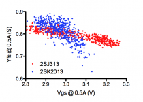
I don't remember seeing that plot before, but I suspect you have shown it elsewhere.
Am I reading it correctly when it appears to show that the Nchannel spread of Yfs (gm) is much higher, than for the Pchannel?
Am I reading it correctly when it appears to show that the Nchannel spread of Yfs (gm) is much higher, than for the Pchannel?
Yes, but still a very decent number of complementary devices with very good matching for both Vgs and Yfs.
For the simple matched-JFET source follower operated at Idss, there is also the Toshiba dual 2SK2145. It has the added inconvenience of the SM package, and at first glance the sources are common. But you can use one section as the current source load of the other by treating the nominal drain of the I source as a source tied to its gate. The two chips seem to be dielectrically isolated, not diode-isolated, and I tested the configuration with some samples. The matching was quite good. Mouser shows stock.The source resistor value is a matter of taste.
The higher the value, the lower the bias and the higher the output impedance.
So I use 0R most of the time.
But using 0R means that you positive bias the JFET with a positive output current.
So it depends on the load you are driving.
It is real bad news that BL is not available anymore.
It also seems that DK has a real left, and probably will follow suit.
They are probably not selling enough loose ones to be bothered in the future.
If I were you I would stock up now.
Alternatives are LSK170, LSK389, BF862, 2SK3557, 2SK2394, ......
Patrick
Depending on power supply rails, I'd recommend using the GR or even the Y bracketed ones for keeping dissipations well within the package rating, which is only 300mW for the combined sections.
Dimitri found the voltage noise to be quite reasonably low iirc, not quite in 2SK170 territory but not a lot worse.
2SK2145 is essentially 2x 2SK209 in one package.
Heat is the problem even with +/-9V.
Some heat sinking is recommended for reliability.
Patrick
Heat is the problem even with +/-9V.
Some heat sinking is recommended for reliability.
Patrick


This will be the final casing of my F5H. It's a milled block of Aluminum that used to be a Russian production radiation detector.
I still have to decide if I want to put the psu outside or put the regulators inside.
I also have to figure out a way of pressing the mosfet on the walls, there is no space for tapping.
Davide
Can't you not drill & tap at the bottom of the radiator fins ?
If they don't line up with the MOFET holes then just use a crosss bar to clamp.
But very original. 🙂
Patrick
If they don't line up with the MOFET holes then just use a crosss bar to clamp.
But very original. 🙂
Patrick
Or use 'single fixture' transistor clamps - they come in a variety of sizes and provide an easy method for even pressure across the 'fet body to heatsink' interface.
Hi Patrick, Seasons greetings and 'all that' ...
Hi Patrick, Seasons greetings and 'all that' ...
As promised a comprehenive description.
http://xen-audio.com/documents/f5ha/F5-HA Description V1.4.pdf
Hi Patrick,
First page of the document says: "The F5-HA PCB was done primarily for our own use". Just wanna ask if there is any plan to make the PCB available, or interested ones should DIY their own boards.
Thanks and Merry Christmas
We have a couple of first version PCBs left which have some minor layout errors.
We already have a revised version with all the corrections in Gerber.
If it is only one of you, you may contact me by email via the forum before Monday.
The board are actually in Sheung Wan right now (lucky you).
Should there be a wider interest (min 10), we'll take the tooling charger for a second run.
But the rest of the team are very busy, so cannot promise prompt delivery.
Patrick
I have to make some decisions on the power supply: the transformer does not fit inside, so I was thinking to put it in a small external box. I have the following possible configurations in mind:
1) psu box with transformer, rectifiers-common mode choke-cap, the amp box will contain 1 or 2 pairs of 7815/7915 and four caps close to the source resistors.
2) put also the regulators with the psu box. ( I have an already populated board for a dual psu that would work well) This will leave space for cross feed circuit. Caps will stay near the source resistors.
The latter would also give more freedom to experiment fancy regulators, using the remote sensing wires I could give a try both to Jan super regulators and Salas(That I also already have.
What do you think?
Davide
It is important to have the caps close to the circuit.
Normally you would want on board regulators as well.
But then if you want to hve cross feed and volume, you will run out of space,from what I can tell.
Have not tried Didden, but Salas was proven not to work on one occasion.
http://www.diyaudio.com/forums/pass-labs/271926-f5-headamp.html#post4288998
Oscillated like hell.
Patrick
Last edited:
I am not going to implement volume control, but cross feed is interesting.
Is there any reason why I should use others than 7815/7915? They would reduce the part count and space a lot. I could probably fit regulators and cross feed. If I use only one pair and think it carefully.
D
Is there any reason why I should use others than 7815/7915? They would reduce the part count and space a lot. I could probably fit regulators and cross feed. If I use only one pair and think it carefully.
D
If it´s possible, I would be interested in one or two PCB´s too. I´ll wait to second run.
cwtim01 will get a V1 PCB. So you are the only one queuing right now.
But I also prefer to only release V2 with all the corrections.
Patrick
Last edited:
To give you an idea :
The 317/337 cap multipliers posted here and in the build thread are 22x32mm.
The Nazar shunt is the same size but a lot more heat.
The cross feed buffers are 48x36mm.
Even if you vero build, you could probably squeeze them in about the same foot print.
Patrick
The 317/337 cap multipliers posted here and in the build thread are 22x32mm.
The Nazar shunt is the same size but a lot more heat.
The cross feed buffers are 48x36mm.
Even if you vero build, you could probably squeeze them in about the same foot print.
Patrick
- Home
- Amplifiers
- Pass Labs
- F5 Headamp ?