Welcome to push-pull, Woody.
The TL431 circuitry sets a voltage window, sort of like the width of a camera view.
Due to variations in the Vgs threshold and resistor values, the output node is not centered at 0 volts.
Similar to moving a camera view, the window can be moved up or down the voltage scale by altering the reference point for the voltage window.
That is what P2 does, P1 sets the voltage difference across both sides of the output and P2 divides it between the two
cviller said:
I'm a bit confused - what amp have you guys been building?
When I made my F4, the service manual said 250mV which corresponds to roughly 0.5A per device - has this changed since?
Nelson' schematic r0 dated 06/4/07 which specifies 200mv / 0.43 amps. There are at least 3 variations, I originally ordered parts using Korben69's bom and they didn't match the r0 schema, so I had to reorder some parts.
ho hum...its all part of the journey.
Ed
The math is quite simple:
U=I*R
0,2=I*0,47 I=0,2/0,47 = 430 mA per fet. This totals to 1,3A for one channel.
This equals 7W classA power @ 8 Ohms
Total dissipation = 65W per channel
U=I*R
0,2=I*0,47 I=0,2/0,47 = 430 mA per fet. This totals to 1,3A for one channel.
This equals 7W classA power @ 8 Ohms
Total dissipation = 65W per channel
Tarasque said:The math is quite simple:
U=I*R
0,2=I*0,47 I=0,2/0,47 = 430 mA per fet. This totals to 1,3A for one channel.
This equals 7W classA power @ 8 Ohms
Total dissipation = 65W per channel
1.3A bias for a push-pull class A means that the output current
is Class A to 2.6A peak, which is 54 watts peak into 8 ohms,
27 watts rms.
😎
Nelson Pass said:
1.3A bias for a push-pull class A means that the output current
is Class A to 2.6A peak, which is 54 watts peak into 8 ohms,
27 watts rms.
😎
Sigh...As alway's...Pappa is right.
If anybody is still interested...
might be useful info for future builders
I've been fiddling and I get 50 degrees on the fets which is 42 degrees on the conrad sinks (mf30-151.5)when I run with bias at 0.49 amps(230mv).
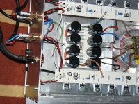
Refer to earlier pics for view of the layout on the sink.
Regards
Ed
might be useful info for future builders
I've been fiddling and I get 50 degrees on the fets which is 42 degrees on the conrad sinks (mf30-151.5)when I run with bias at 0.49 amps(230mv).
Refer to earlier pics for view of the layout on the sink.
Regards
Ed
jacco vermeulen said:Welcome to push-pull, Woody.
The TL431 circuitry sets a voltage window, sort of like the width of a camera view.
Due to variations in the Vgs threshold and resistor values, the output node is not centered at 0 volts.
Similar to moving a camera view, the window can be moved up or down the voltage scale by altering the reference point for the voltage window.
That is what P2 does, P1 sets the voltage difference across both sides of the output and P2 divides it between the two
A beautiful presentation, Jacco. This one goes into my F4 folder with all the other excellent adjustment descriptions!
Thanks,
John🙂

Member
Joined 2002
I'm looking at the F4 schematic and it says D2-D1 are 2n4736, when i did my oder i was shipped 1N5235B Will this work ?
better to ask than blow things up 🙂
better to ask than blow things up 🙂
jleaman said:I'm looking at the F4 schematic and it says D2-D1 are 2n4736, when i did my oder i was shipped 1N5235B Will this work ?
better to ask than blow things up 🙂
Have you looked up the datasheets of the two diodes in question?
Magura 🙂
Member
Joined 2002
Magura said:
Have you looked up the datasheets of the two diodes in question?
Magura 🙂
Yes but didn't find much,
1N4736 2005-10-20 1N2082, 1N20B1, 1N4149, 1N4736632, 1N4758, 1N5036, 1N52, 1N5234B, 1N5235A, 1N5237B, 1N5248, 1N5248A, 1N5257, 1N5363, 1N5404, 1N6V8, 1N97C6V8, 2082, 20B1, 20B2, 5257, 74HC14F3A, 74HC4F3A, 9551, 97C19, 97C5V6, 97C6V8, CD54HCA4F3A, ECG177, ECG5071A, ITTZPD5.6, ZPC5.1, ZPC51
http://www.datasheets.org.uk/datasheets/1N4736.html
Member
Joined 2002
Magura said:
Mine are 6.8V zener's the others are 6.8 🙂 so im good 😛 It's always better to ask than assume, and cause smoke 😛
jleaman said:
Mine are 6.8V zener's the others are 6.8 🙂 so im good 😛 It's always better to ask than assume, and cause smoke 😛
Not to rain on your parade, but a simple search would have sorted you out, it would have been faster for you, and less annoying for us.
It took me like 20 seconds to find the answer here at diyaudio, using the less than optimum diyaudio search engine....by simply typing the part number in the search fiels and tick show results as posts.
Try it sometime.
Magura
Member
Joined 2002
So i set P1 and P2 to low, i think zero, because it clicked, plugged in the variace put in a 1amp fuse and turned the variac up a little, i ca hear it huming but thats normal, i turned it up more to about 60V ac ( reading the dial on the viaac ) and checked the Dc offset on the speaker to be about 6V EKKS, then checked R18 with my meter to see 50mv, after a min or so the 1am fuse blew, i checked the temperature on the fets and they were getting warm.
Any thing im doing wrong ? or should check again, i did tripple check the values and make sure no shorts etc etc the reglar stuff,
I did check the PSU at first, powered it up and it was fine. So the PSU is working a.o.k.
Jase
Any thing im doing wrong ? or should check again, i did tripple check the values and make sure no shorts etc etc the reglar stuff,
I did check the PSU at first, powered it up and it was fine. So the PSU is working a.o.k.
Jase
I think your pots may be off, I saved these posts for initial pot setting:
Post #1305
Does any one have some suggestions for first power up of the F4, i mean after populating the boards wiring every thing up and double checking every thing, what should be done ? What should the pots be set at ?
Hints - Help ?
post #1306
P1 set to Maximum , P2 in the centre position (~ R5 value)
The reference voltage for a TL431 is 2.5 Volts.
With P1 set at 5K there's roughly 6 Volts across the gates of the OP T's, at the zero setting 8 Volts.
Post #1307
P1 set to Maximum , P2 in the centre position (~ R5 value)
The reference voltage for a TL431 is 2.5 Volts.
With P1 set at 5K there's roughly 6 Volts across the gates of the OP T's, at the zero setting 8 Volts.
Post #1308
The 2.5 volts is a fixed value for the TL431.
By turning P1 you're changing the current flowing through P1 and the 10K resistor.
The changing current also changes the voltage drop across the 22K above them, altering the voltage across the gates.
The voltage across the gates is at the lowest setting with P1 set at 5K, = roughly 6 Volts.
The average voltage on the gates of the 240/9240 that's needed to open them is 3 volts, makes 6 Volts for the both of them.
On the top of the schematic there's a 1K resistor and the 5K pot P2.
In the bottom section is something like 3.32K (IIRC, acroidiot is stuck again)
For symmetry, P2 should be set at 3.32K-1K= 2.32K, so in the middle.
That way the voltage on the gate of the 240 equals that on the gate of the 9240, and they open at the same rate when you crank the bias up.
First, set the bias low by turning P1, then adjust P2 to get rid of DC offset.
Let the amp warm up, then raise the bias higher and check DC again.
Member
Joined 2002
yes, maybe, however i didn't even get it to fully power up even with the pots turned to zero.
I can re-try this again, ill set P1 to max, then P2 in the middle. Kinda hard to measure now that they are soldered to the board and the board is mounted.
Jase
I can re-try this again, ill set P1 to max, then P2 in the middle. Kinda hard to measure now that they are soldered to the board and the board is mounted.
Jase
- Home
- Amplifiers
- Pass Labs
- F4 power amplifier