C1 and C2
I have some Black Gate 220uF 6.3V NX caps. Do you think it'safe to use them at C1 and C2?
From my understanding, the voltage between C1 and C2 is regulated by Q11, so it can't be much more than 8V?
I have some Black Gate 220uF 6.3V NX caps. Do you think it'safe to use them at C1 and C2?
From my understanding, the voltage between C1 and C2 is regulated by Q11, so it can't be much more than 8V?
Re: C1 and C2
So you think the voltage is 8V and the cap is 6.3, now there you have given yourself the ansver.
'Magura 🙂
niner said:I have some Black Gate 220uF 6.3V NX caps. Do you think it'safe to use them at C1 and C2?
From my understanding, the voltage between C1 and C2 is regulated by Q11, so it can't be much more than 8V?
So you think the voltage is 8V and the cap is 6.3, now there you have given yourself the ansver.
'Magura 🙂
What I mean is from pos of C1 to neg of C2 is around 8V, so voltage across C1 or C2 should be about 4V. But I could be wrong, that's why I asked the question.
Re: Yunick's F4 pics and grounding
Thanks alot Geo,
Your advice did the trick 🙂 now it's all working correct ...
Thank you Nelson for sharing this eminent circuit 🙂
cherhit said:Thanks Nelson.
Yunick, looking at the pics of your boards, I'm wondering how you have that circuit grounded. As I understand from Nelson's answer in the above post, the GND next to SG should go to supply ground. I see wires connected to GND at the other end of the board, but as I see it, that GND only provides a connection to supply ground for C5 & C6 if used.
Geo
Thanks alot Geo,
Your advice did the trick 🙂 now it's all working correct ...
Thank you Nelson for sharing this eminent circuit 🙂
15A regulated PSU for F4 headphone amp
Hi Guys,
This is the shematic of 15A regulated PSU, designed by a dealer, named UCC, in Taiwan. Some of you may know him and his two famous products, ultimate mini-regulator and PP capacity.
Here is the shematic.
And the reference website talking about how to set the out voltage.
set the output voltage
I think this regulator may fit the F4 headphone amp, so I try to layout it in these days. Here it the layout.
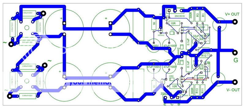
cheers!
Peleus
Hi Guys,
This is the shematic of 15A regulated PSU, designed by a dealer, named UCC, in Taiwan. Some of you may know him and his two famous products, ultimate mini-regulator and PP capacity.
Here is the shematic.
An externally hosted image should be here but it was not working when we last tested it.
And the reference website talking about how to set the out voltage.
set the output voltage
I think this regulator may fit the F4 headphone amp, so I try to layout it in these days. Here it the layout.
cheers!
Peleus
Re: 15A regulated PSU for F4 headphone amp
in your boots I'll try F4 for HP first without any super duper reg ;
my next step will be non reg - CLC or CRC mucho caps PSU ;
try it and decide what's better
cascoded 317 (and 337) will do the same job ( or even better ) as that proposed reg , sound wise
Peleus said:Hi Guys,
This is the shematic of 15A..........
Peleus
in your boots I'll try F4 for HP first without any super duper reg ;
my next step will be non reg - CLC or CRC mucho caps PSU ;
try it and decide what's better
cascoded 317 (and 337) will do the same job ( or even better ) as that proposed reg , sound wise
Transformer power rating.
Hi. Can you tell me the different power rating requirements for the different First Watt amplifier starting with the F1:
F1,2,3, dual sec 18Vac
F4 needed transformer?
Is there a real advantage of building the F4 compare to the F1 simplicity (no need to match output device)?
I'm planning to drive a pair of Lowther with it using a crossover network.
Thanks...
SB
Hi guys!
I finaly made my F4 and it works!!! kind of.....
The problem is that I can't turn the bias more than 0.10V on the 0.47 ohm rezistors. I have set the P2 in order to have 0V DC at the output and turned P1 to reach 0.25V on the 0.47 rezistors but I can't reach more than 0.10V - What should I do?
The power suply delivers 2x19.5V with 2 power stages conected!
On R8 (22K) I got 5.4V and on R9 (10k) I got 2.5V
😕
I guess you problem can be solved by adjusting the resistors around TL431.
http://www.diyaudio.com/forums/showthread.php?postid=1169323#post1169323
(note: I used an old revision of the schematics)
http://www.diyaudio.com/forums/showthread.php?postid=1169323#post1169323
(note: I used an old revision of the schematics)
HI cviller !
You sugest me to change R9 to 5K and P1 to 10K and try to anjust the bias like that ????
You sugest me to change R9 to 5K and P1 to 10K and try to anjust the bias like that ????
No, just try to lower R9, if the problem is to get enough voltage diff between gates of p an n types. Try to measure this gate diff voltage first - it should be around 8V.
Yeap, it is 7.8V
I will try to lower R9 to about 8k.
Thank's for helping out!
If it will work fine I will post some pictures tomorow!
I will try to lower R9 to about 8k.
Thank's for helping out!
If it will work fine I will post some pictures tomorow!
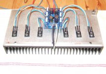
vitalstates said:nearly there......
Pretty. I looked as close as your pic allows, so pardon me if I'm wrong, but it seems to me that your power mosfet gate resistors are supposed to be very close to the gate pin.
carpenter said:
Pretty. I looked as close as your pic allows, so pardon me if I'm wrong, but it seems to me that your power mosfet gate resistors are supposed to be very close to the gate pin.
They work just fine like this is done.
So no worries.
Magura 🙂
While I've never gone so far as to have a long distance challenge, I have run lengths up to ten or twelve inches from Gate stopper to Gate without problems. There are a lot of variables in play, though, and I prefer to keep it under three inches when I can. That's in bench circuits. Once I get to the PCB stage, I'm generally in the .2 inch realm.
Grey
Grey
Regarding distance (long leads being acceptable between gate and resistor), is this a general rule, or does it only apply to certain fet amplifiers. I was under the impression that the resistor had to be close to the fet.
I stand corrected.
I stand corrected.
Thanks for the positive feedback chaps. I will post better pics next week as I had to borrow this camera while mine is somewhere in slovenia with wife on business.
hook up today, fingers crossed.
Regards
Ed
hook up today, fingers crossed.
Regards
Ed
- Home
- Amplifiers
- Pass Labs
- F4 power amplifier