Mr. PAss how did you choose the values for the R5,R6.R7.. (the gate bias resistors)? What would happened if they were 200K or 500k for instance?
Thanks for your reply Magura..
- Are you using old sil pads?
Yes...
- Is the temperature stable?
It's getting hot... but I have not had it turned on for very long ...
- Try adding a lets say 10uF cap in parallel with the hot input (to make sure you don't induce DC)
Will do .. I tried using both my laptop and preamp as source with same result...
Yunick said:Thanks for your reply Magura..
- Are you using old sil pads?
Yes...
- Is the temperature stable?
It's getting hot... but I have not had it turned on for very long ...
Well, loose the old sil pads, those are not for recycling 🙂
Good old mica and grease is still a fine solution. Sil pads are for production use, as they need the correct torque to work well.
Magura 🙂
Magura said:
Well, loose the old sil pads, those are not for recycling 🙂
Good old mica and grease is still a fine solution. Sil pads are for production use, as they need the correct torque to work well.
Magura 🙂
Thanks for your advice.. I will order new ones on monday.. 🙂
Didn't know they where so fragile.. 🙁
Yunick,
I'm a little concerned that the resistors can't lay flat against the pcb. Not enough room...
I've ordered these boards and hoped to have a professional appearance.
If the resistor leads are bent and tucked under the resistor body, will the adjoining resistor leads clear one another? I see that the resistors are tail-gating (for lack of a better term).
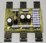
Also, I noticed that your heatsink isn't very polished where the fets make contact. Could this be creating a weak thermal contact?
You've got a pretty clever way of marking your fets...😀 How did you do that?
I'm a little concerned that the resistors can't lay flat against the pcb. Not enough room...
I've ordered these boards and hoped to have a professional appearance.
If the resistor leads are bent and tucked under the resistor body, will the adjoining resistor leads clear one another? I see that the resistors are tail-gating (for lack of a better term).
Also, I noticed that your heatsink isn't very polished where the fets make contact. Could this be creating a weak thermal contact?
You've got a pretty clever way of marking your fets...😀 How did you do that?
bogdan_borko said:Mr. PAss how did you choose the values for the R5,R6.R7.. (the gate bias resistors)? What would happened if they were 200K or 500k for instance?
These are choices bounded by several considerations:
1) Minimize loading of the front end JFETs, which argues for
higher values.
2) Ensure enough current for the TL431 which wants 300 uA
minimum.
3) Decide on a reasonable ratio for the values with regard to
supply filtering and bootstrapping from the output stage.
You will find that you do not need precise values, but as you
wander far away from these, you will take a performance hit
somewhere.
😎
carpenter said:Yunick,
I'm a little concerned that the resistors can't lay flat against the pcb. Not enough room...
I've ordered these boards and hoped to have a professional appearance.
If the resistor leads are bent and tucked under the resistor body, will the adjoining resistor leads clear one another? I see that the resistors are tail-gating (for lack of a better term).
Also, I noticed that your heatsink isn't very polished where the fets make contact. Could this be creating a weak thermal contact?
You've got a pretty clever way of marking your fets...😀 How did you do that?
Hi Carpenter,
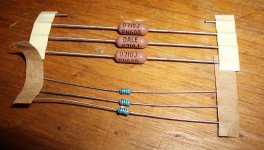
The boards are designed with miniature resistors in mind.. I can't remember what they were called but Peter Daniel explained this in the groupbuy thread.. I use regular 0.6w metalfilm resistors from elfa.se..
There is plenty of space under the resistor body so there should not be a problem.. I did this on my A30 with boards from Peter with good results.
The heatsinks are from conrad heatsinks in Australia.. This is how they look when I recived them.. I use them in my babelfish and previous in my A30..
The fets come from Tarasque here on the forum.. He have a automatic matching rig.. don't know how that works but the markings are very handy 🙂
The resistors are Phoenix/Vishay SFR16S, page 1686 in the current Digi-Key catalog. Very nice and not that expensive. I have used them in other items from Peter and in BrianGT's boards for Alephs.
Malotron said:
the Phoenix SFR16S are swell but stuffing a board with them is like training fleas to play dead. 😉
-Mal
well - all you need to do this properly is plastic leads former and few beers ;
after few beers , who cares for resistors and amps?

Resitors
The Panasonic miniature 1/4 watt resistors as shown on Digi-Key catalog page 1678 will fit Peter's boards.
http://dkc3.digikey.com/PDF/T073/P1678.pdf
Geo
The Panasonic miniature 1/4 watt resistors as shown on Digi-Key catalog page 1678 will fit Peter's boards.
http://dkc3.digikey.com/PDF/T073/P1678.pdf
Geo

Malotron said:Beer is a familiar subject here in the NW. 🙂 And da "ducks." 🙄
-Mal
My god, we're almost neighbors. Go Beavers.........

F4 circuit ground question
In the First Watt F4 r0 6/4/07 schematic, is there a ground connection that connects to the power supply ground? I see a ground at R2. Does this go to supply ground?
Thanks
Geo
In the First Watt F4 r0 6/4/07 schematic, is there a ground connection that connects to the power supply ground? I see a ground at R2. Does this go to supply ground?
Thanks
Geo
Re: F4 circuit ground question
Hi George,
Yes, all references to ground in that schematic, including the
implied load to ground, go to the same point.
😎
cherhit said:In the First Watt F4 r0 6/4/07 schematic, is there a ground connection that connects to the power supply ground? I see a ground at R2. Does this go to supply ground?
Hi George,
Yes, all references to ground in that schematic, including the
implied load to ground, go to the same point.
😎
My god, we're almost neighbors. Go Beavers.........
Always a hot amp and cold beer at the ready for DIY’ers passing through Tracktown... Beavers fans included. 😉

Yunick's F4 pics and grounding
Thanks Nelson.
Yunick, looking at the pics of your boards, I'm wondering how you have that circuit grounded. As I understand from Nelson's answer in the above post, the GND next to SG should go to supply ground. I see wires connected to GND at the other end of the board, but as I see it, that GND only provides a connection to supply ground for C5 & C6 if used.
Geo
- Home
- Amplifiers
- Pass Labs
- F4 power amplifier