How far is this from the airport?
Well, if you aren't carrying too many F4's then you can take our rapid transit system, BART, directly from the airport now. Then switch to a bus to go over the hill to the site. Otherwise, a van from the airport shared with other passengers isn't too bad.. The driver can take you to the closest hotel to the event. Then take a taxi.
I'm sure we can get youto the event if you decide you really are coming. Places to stay at member's houses seem to be rare unless someone posts here that they can take someone..
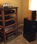
Variac said:Some interest was expressed on the Burning Amp thread as to how I am coming along. I'm going for a bit of a classic look..
...
Variac..
Hey that's literally a component rack...very cool!
19th century mad scientist look
Captain Nemo, your F4 is ready!
A shot of the "bizarre heatsink tower" please.
-Mal
pic of maple/concrete rack
Albums I'm listening to through my F4:
Brokeback Field Recordings
Talking Heads "77"
Sparklehorse It's A wonderful Life
Neil Young Live - Massey Hall 1971
Attachments
Thanks guys for your very kind comments. I hope my wife feels similarly 
I think she suspects though- it is being built on the kitchen table!
I have to leave the Bizarre Heatsink for a surprise at the Burning Amp show. It is more big than bizarre anyway..
Choky, I like to keep my picture off of the web so I won't be hunted down by angry ex-members, but you found it!! Now I'm ruined 😉
Variac
Variac said:.........
Choky, I like to keep my picture off of the web so I won't be hunted down by angry ex-members, but you found it!! Now I'm ruined 😉
Variac
😉
I'm always here to serve ..............
hehe - sort of half Mod .............
'cause you are here to serve & protect

Member
Joined 2002
jleaman said:Ok, so who has the Lates F4 Bom, ? Can i have copy plz..
hm.... maybe I'm just overlooking something here but - what is exactly BOM and why you need it
that nomenclature always slips near me...... is it plain sheet of elements or with included info " where to purchase,code for purchase etc "
?
Zen Mod said:
hm.... maybe I'm just overlooking something here but - what is exactly BOM and why you need it
that nomenclature always slips near me...... is it plain sheet of elements or with included info " where to purchase,code for purchase etc "
?
For example, here is
Jim's BOM
😉
mpmarino said:
than I'm lucky......... I always know where to buy my drek ........

at Harvey Keitel's Tobaco Store .......
This is an up to date one I believe.
http://www.diyaudio.com/forums/attachment.php?s=&postid=1263192&stamp=1185337158
Remember that Nelson changed the values for the resistors afterthe initial post
So any prudent builder would first go to Nelson's site as mentioned in the first post and find the file about the F4 , then download the entire NEW owner's manual
Then compare the BOM in question with the
schematic (Version 0 dated 6/4/07 I believe, but check for yourself.. )
the older BOM's are good resources for alternate parts- if they are changed to the correct value if required.
I was very brave and ordered different resistors , 3w resistors (got 5w) trimmer pots (bourns- mentioned in a different BOM, bridge, power caps, It was fun to mix and match and feel like I actually had an opinion of what is best!!
Digikey worked for me, except for the resistors, 'cause of my weird resistor desires!! and they sent me a new catalog twice as thick as my 5 year old one!!
Last edited:
Heatsink calc
A friend is helping me build my F4s (archetypal British understatement). He has done some calculations to determine how serious the heatsinks need to be but suggested I post the calcs on this thread to see if others think they stack up:
Each device is passing 0.43A so at 23v
(minus 0.2v
dropped across the resistor) the total power dissapated at
idle is 6 *
0.43 * 23 - 0.2 ) = 59W.
So, for a running temp of 50Deg, and room at 25deg, the
heatsink will be
at 25deg above ambiant. So the total thermal resistance
needs to be
25/59 or 0.424 C/W
The chip to case thermal resistance of the mosfet is 0.24
C/W, so for 6
devices thats 0.04 C/W, assuming efficient coupling from
the device to
the heatsink,
Assuming 1 C/W insulation for the device to heatsink,
again, thats in
parallel, so thats .16 C/W, so a total Chip to sink of 0.2
C/W, so that
leavs us needing
0.424 - 0.2 = 0.224 C/W
Any comments?
Re: Heatsink calc
every day calculus :
U=23 x 2
I=,43 x 3 (3 verticals)
Ptot = 46 x 0,46 x 3 ~64W
Tmax ~ 50C
Tamb~ 25
Dt=25
Rth = (25 / 64) x 0,85 = 0,33
so-you'll have ~ 50C at heatsink
who cares for mosfets?

Studley said:A friend is helping me build my F4s (archetypal British understatement). ..............
Any comments?
every day calculus :
U=23 x 2
I=,43 x 3 (3 verticals)
Ptot = 46 x 0,46 x 3 ~64W
Tmax ~ 50C
Tamb~ 25
Dt=25
Rth = (25 / 64) x 0,85 = 0,33
so-you'll have ~ 50C at heatsink
who cares for mosfets?

All aspects complete:
Rth____________________°K/W_____delta T
Heatsink_________________0,3_______20,7
Tmount-Heatsink___________0,1_______6,9
Isolator-Transistormounting__0,3_______3,5
Isolator-Transistor_________0,2________2,3
Transistor-Junction-case_____0,83______9,5__IRFP240 = 0,83
Dissipation W/transistor_____11,5____117watt total
amount of transistors________6
dissipation per channel______69W
dissipation stereo__________138W
rail voltage________________23V
total bias_________________1,5A
ambient T ________________25°C_____77°F
Junction T_______________67,9°C____154,21°F
Mounting temperature_____52,6°C____126,68°F
Heatsink temperature_____45,7°C_____114,26°F
Variac said:My power supplies and chassis are about done,,,
but I got my order from Digikey today. The mica insulators for the output devices are a tiny bit SMALLER than the metal on the back of the MOSFETS. It seems to me that the spacing should be enough, with the low voltage.. but if not the consequences would be very unpleasant.. What do you think?
with np's amps you should always leave wide margins
-most of his amps run hot- use insulators bigger than
the devices thats what i reckon
cheers
😉
Hi, I am the person Studly has asked to do the build, can I just gheck something?
Should that not be
Ptot = 46 * 0.43 * 3 = 59.34
(ignoring the small amount of power that will be dissapated in the resistors)
But I am not sure where
every day calculus :
U=23 x 2
I=,43 x 3 (3 verticals)
Ptot = 46 x 0,46 x 3 ~64W
Tmax ~ 50C
Tamb~ 25
Dt=25
Rth = (25 / 64) x 0,85 = 0,33
so-you'll have ~ 50C at heatsink
Should that not be
Ptot = 46 * 0.43 * 3 = 59.34
(ignoring the small amount of power that will be dissapated in the resistors)
But I am not sure where
Rth = (25 / 64) x 0,85 = 0,33{/quote]
Comes from. Ok the Chip to case on the device is 0.85, but as you have 6 in parallel, then if you are using the total power diss, it should be 0.85/6 and subtracted not multipled.
Maybe I am reading this wrong, is the target a heatsink temp of 25 above ambiant or is it the chip temperature?
lurcher300b said:Hi, I am the person Studly has asked to do the build, can I just gheck something?
Should that not be
Ptot = 46 * 0.43 * 3 = 59.34
(ignoring the small amount of power that will be dissapated in the resistors)
But I am not sure where
Rth = (25 / 64) x 0,85 = 0,33{/quote]
Comes from. Ok the Chip to case on the device is 0.85, but as you have 6 in parallel, then if you are using the total power diss, it should be 0.85/6 and subtracted not multipled.
Maybe I am reading this wrong, is the target a heatsink temp of 25 above ambiant or is it the chip temperature?
well- every-day calculus is example what is needed,what not ;
let's not over-engineer what is just for engineering .
forget about resistor dissipation in overall picture- there are just 6 of them,each with less than 0,1W dissipation
........ (25/64) x 0,85........
25 is Dt between heatsink and air [C]
64 is sum of dissipation [W]
0,85 is just experience factor , nothing else - where are summed usual losses etc.
presuming that mounting of output devices is "good enough" or "proper" (in other words) , shooting at heatsink temperature instead on chip temperature is completely sane ;
you must shoot chip temperature in case when output devices are much closer to their limits than in this case
here's how i see it:
Rth(j-a) = (Tj max - Tamb) / Ptot
Ptot = 46 * 0.43 * 3 = 59.34
where:
T(j max) is the max of the junction temp we want to allow
Ptot is Vrails * Ibias
Rth(junction-ambient) = Rth(junction-case) + Rth(heatsink) = 0,83 (for IRFP240) + Rth
the matter is to know exactly which Tj you want... according to IRFP240 datasheet it seems that Tj max is 125°C but i guess that safe operating temp will be lower.
Let's say Tj max 100°C, so your heatsink should have Rth = 0,43°C/W
Is it correct? 😕
Hi~
I've got an idea about using a "small" F4 amp shematics as headphone amp. What I mean "small" F4 amp is substituting orignal 3 pairs of mosfets with a pair of BD139/140 and putting the voltage of PS to +-15.
Can it work? Or, any suggestion or comments will be welcome.
I've got an idea about using a "small" F4 amp shematics as headphone amp. What I mean "small" F4 amp is substituting orignal 3 pairs of mosfets with a pair of BD139/140 and putting the voltage of PS to +-15.
Can it work? Or, any suggestion or comments will be welcome.
- Home
- Amplifiers
- Pass Labs
- F4 power amplifier