luvdunhill said:
Also, maybe with so many people buying F4 PCBs there can be a group by of the R-Theta heatsinks again?
Hi, I believe diy member grataku has two of the r-theta 11" X 11" heatsinks from the old PD group buy available, I talked to him last week. Here is a link for you to email him if curious.
http://www.diyaudio.com/forums/showthread.php?postid=772853#post772853
Stan
Mr Mod
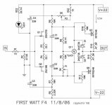
On this lousy schematic you made, have you built and tried it or just talked about it🙄
well..
Hows about takin NP's Rev0 and gettin rid of the 240/9240 for 610/9610 > for a set of compression drivers - or would they explode
You mentioned 540/9540 before, but that's not stupid enough....
and I'd have to buy them
and I'm dreadfully cheap
bahhh forget it. They'd blow right up Better with just 1 pair on output a la mini I guess..... a perfect match 1 is
On this lousy schematic you made, have you built and tried it or just talked about it🙄
well..
Hows about takin NP's Rev0 and gettin rid of the 240/9240 for 610/9610 > for a set of compression drivers - or would they explode
You mentioned 540/9540 before, but that's not stupid enough....
and I'd have to buy them
and I'm dreadfully cheap
bahhh forget it. They'd blow right up
Better with just 1 pair on output a la mini I guess..... a perfect match 1 isAttachments
mpmarino said:Mr Mod
On this lousy schematic you made, have you built and tried it or just talked about it🙄
well..
Hows about takin NP's Rev0 and gettin rid of the 240/9240 for 610/9610 > for a set of compression drivers - or would they explode
You mentioned 540/9540 before, but that's not stupid enough....
and I'd have to buy them
and I'm dreadfully cheap
bahhh forget it. They'd blow right up
you can use 610/9610 for that
go with lower voltage too,say +/- 15 volts and keep current in range of 350-500mA
that will be ~ 8W per mosfet,16 per channel and that's easy to coolllllllllllll
hey- I didn't build that ; why should I .....I know it works 😉
Hi everyone,
Some parts questions:
1)Can i use 0.125W resistors for the circuit other than the 3w .47r's;
2)Is the 1n4736 same as the 2n4736? Can't seem to find the 2n4736 locally.
Thanks
Chuck
Some parts questions:
1)Can i use 0.125W resistors for the circuit other than the 3w .47r's;
2)Is the 1n4736 same as the 2n4736? Can't seem to find the 2n4736 locally.
Thanks
Chuck
angchuck said:Hi everyone,
Some parts questions:
1)Can i use 0.125W resistors for the circuit other than the 3w .47r's;
2)Is the 1n4736 same as the 2n4736? Can't seem to find the 2n4736 locally.
Thanks
Chuck
1n is always dreky diode,whatever that means
2n is always dreky transistor,whatever that means
hehe- and whoever wrote that
just use any 6V8 zener
that will be ~ 8W per mosfet,16 per channel and that's easy to coolll.....
Use just a pair per channel of 610/9....?? Why not toss a couple more at it? The capacity-ance would still be dirt???
hey- I didn't build that ; why should I .....I know it works
bla bla blaaaa🙄 😉
mpmarino said:
Use just a pair per channel of 610/9....?? Why not toss a couple more at it? The capacity-ance would still be dirt???
bla bla blaaaa🙄 😉
ya wanna feed tweets or massage chair ?
I told you that you need all of finesse you can get
what preamp you have? mebbe you can use just xformers between preamp and tweets........
ya wanna feed tweets or massage chair ?
both.
I told you that you need all of finesse you can get
OK, I'll go buy a case of shampoo.
point taken.
mpmarino said:
OK, I'll go buy a case of shampoo.
Why don't you try a bottle of wine? A bit harder to drill, I grant you, but the content taste much better (ask Vix).
Manu said:
Why don't you try a bottle of wine? A bit harder to drill, I grant you, but the content taste much better (ask Vix).
naah- it's easy
Attachments
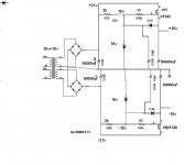
What if we take Mr. Mod 's crippled F4 as above (no, not the corkscrew) with 610/9610 outputs and did this PSU. Yes, I know it's a completely stolen Nelson schematic that was destroyed by myself. I wanna put that finesse amp together for the 902s. I'll gall it my shampoo amp. Will it blow up?
Mr Mod ?
's crippled F4 as above (no, not the corkscrew) with 610/9610 outputs and did this PSU. Yes, I know it's a completely stolen Nelson schematic that was destroyed by myself. I wanna put that finesse amp together for the 902s. I'll gall it my shampoo amp. Will it blow up?Mr Mod
?Attachments
mpmarino said:What if we take Mr. Mod
Mr Mod
you can ditch one zero of all caps you drew,if you stay in ballpark of ,say 350mA Iq per channel.
or- you can use just those 30.000 and ditch everything after
your choice- I think that you'll hardly hear difference,at least on these lousy squakers
mpmarino said:Should I ditch the first or last zero?
dunno........
in second thought......it's better to ditch all 3-s in first and all 6-s in last bank

Zen Mod said:
dunno........
in second thought......it's better to ditch all 3-s in first and all 6-s in last bank
Got it! Thanks!
I am in for designing my own pcb's to fit my need's.
I have tried to mockup a output board, for IRFP240 / IRFP9240, which fit my heatsinks perfectly... Only difference is how the Zener diode must be turned. The mosfets are soldered under the Cu traces, and the gate, source resistor and zener-diode are ofcause soldered on the component side of the pcb's (Witch i had to make 8 pcs. of for 2mono block's)
Any comment's and suggested modifications are very welcome ! 😉
Jesper 😎
Attachments
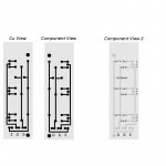
Jesper, you might want to make the tracks as wide as possible.
Especially the Source and Drain tracks would benefit from a bit wider tracks.
Steen🙂
Especially the Source and Drain tracks would benefit from a bit wider tracks.
Steen🙂
lykkedk said:I am in for designing my own pcb's to fit my need's.
Any comment's and suggested modifications are very welcome ! 😉
Do you plan any thermal coupling between the N and P mosfet banks?
I think that would be wise in terms of dc stability.
Thank's i will make the traces as wide as possible.
For the thermal coupling i don't know, i don't think it's possibly with my heatsinks...
I will use 1 heatsink for the irfp240 and another for irfp9240, btw.
I havent really thought about that

For the thermal coupling i don't know, i don't think it's possibly with my heatsinks...
I will use 1 heatsink for the irfp240 and another for irfp9240, btw.
I havent really thought about that
- Home
- Amplifiers
- Pass Labs
- F4 power amplifier