Doesn't that change the temperature of every component in the circuit, though? I figured we would want some components like the output FETs to be considerably hotter than, say, the input JFETs. When I run simulations like this by setting TEMP globally, the front-end of the amp gets out of control (e.g. IDSS of JFETs doubles). So, I can't get the output stage "hot enough" without the input stage falling apart.
don't ask me ...... not exactly LTSpice guru ..... far from it
what is exact test saying me is more in sideway manner - same test made on sim of known circuit (say Aleph J) , then comparison
what is exact test saying me is more in sideway manner - same test made on sim of known circuit (say Aleph J) , then comparison
Doesn't that change the temperature of every component in the circuit, though? I figured we would want some components like the output FETs to be considerably hotter than, say, the input JFETs. When I run simulations like this by setting TEMP globally, the front-end of the amp gets out of control (e.g. IDSS of JFETs doubles). So, I can't get the output stage "hot enough" without the input stage falling apart.
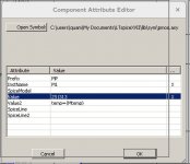
Yes, every component will step with the TEMP setting unless that component has an explicit "TEMP={expr}" setting its VALUE or VALUE2 slot. Below is the LTSpice popup menu for my 2SJ313 whose temperature is determined by the SPICE variable MTEMP. Unfortunately, some of the SPICE models, including those IXYS for the hocky-pucks, do not accept TEMP as a parameter and use the global TEMP instead.
Attachments
Thanks, Lynn. This confirms my findings about the IXYS models not taking a TEMP argument. I didn't think to try TEMP with the other parts after seeing it fail for the IXYS.
Thanks, Lynn. This confirms my findings about the IXYS models not taking a TEMP argument. I didn't think to try TEMP with the other parts after seeing it fail for the IXYS.
I let the IXYS parts be controlled by the global TEMP variable and computed values for the other parts using expressions involving TEMP. Since the FE parts should come up the their "stable" temperatures fairly quickly since the thermal mass of the main heatsink is not involved. This suggests that TIME should be another variable in the equations for part temperatures. At some point you must throw your hands up and settle for ballpark guesses about the temperatures.
Another comment about device temperatures: The FE bias is most influenced by the JFET temperatures unless the JFET Idss is near the zero tempco point of around 12mA. See JFETs: The New Frontier, Part 1. With the right circuit, the 2nd stage J313/K2013 temperature behavior is not a problem.
Testing Mongrel F4 beast
Got bored of hockey pucks. Been there done that.
Time to give the title of this thread some meaning.
Fully tested just need to hook up speakers and listen.
It was an idea I had maybe 3 years ago. Happy to say it works like glue.
Let's see who notices the differences first.
Got bored of hockey pucks. Been there done that.
Time to give the title of this thread some meaning.
Fully tested just need to hook up speakers and listen.
It was an idea I had maybe 3 years ago. Happy to say it works like glue.
Let's see who notices the differences first.
Attachments
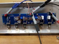
That is a FirstWatt F4 board.
You eliminated one of the IRFP240s and reduced the degeneration of the remaining two to 50mOhms. You totally eliminated the degeneration of IRFP9240s. I am not sure how you stabilize the bias.
I suspect this might resemble the positive phase of the XA30.8 output stage, but with minimal degeneration.
No need for bias stabilisation.
It goes from 1.5A cold to 2A at operating temp.
Takes around 15minutes to get to about 1.9A and probably 30 mins to get to 2A (roughly speaking)
DC off set goes from -150mV (turn on thump) to less than -50mV within 5 seconds, and settles to around 1mV within 10 minutes.
My heatsinks are 500mm long by 150mm tall, can't remember fin depth (I'm on the toilet).
What does the harmonic spectrum look like? It should have a decent damping factor even without feedback, maybe around 80, just a guess.
Damping factor is around 115
I can give simulated results for distortion now.
I can measure real distortion tomorrow on the analyzer.
I can give simulated results for distortion now.
I can measure real distortion tomorrow on the analyzer.

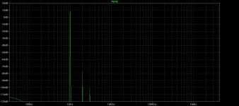
I can get much lower distortion but the intent was to increase the distortion to closer to how I like.
I will probably play around with this a bit more maybe adding up to 0.02% 2nd harmonic.
I will probably play around with this a bit more maybe adding up to 0.02% 2nd harmonic.
Last edited:

Those are impressive simulation results. Your board appears to preserve the F4 JFET buffer stage. To use the F4 in an audio system, a good front end is necessary to provide a voltage gain up to 20V peak. I played around with the BA3 gain stage, the Impasse Valve preamp, and my own Curly-F4 gain stage. I liked the sound of the Impasse best, but getting good 6SN7 tubes can be a problem.
can you flip the phase of 2nd?
aren't IRFPs much more friendly than bigbada$$pcks ?
Yeah much easier to deal with, and cheaper and less charging capacitance etc etc.
Win win for the peasants. Hahaha
Positive 90 degrees phase lag in ltspice corresponds to perfect negative phase 2nd harmonic.
I can also switch it to positive phase harmonic.
Last edited:
Those are impressive simulation results. Your board appears to preserve the F4 JFET buffer stage. To use the F4 in an audio system, a good front end is necessary to provide a voltage gain up to 20V peak. I played around with the BA3 gain stage, the Impasse Valve preamp, and my own Curly-F4 gain stage. I liked the sound of the Impasse best, but getting good 6SN7 tubes can be a problem.
I'm going to plug it directly to CD player and keep throwing various speakers of differing sensitivity at it till I am happy with the SPL.
It may never see more than 2V rms.
Worst case scenario I build something like Zen Mods newest preamp, or one of my own designs for 6dB voltage gain, in which case no more than 4V rms.
With 2-N(IRFP240) 3-P(IRFP9240) FET arrangement, the IRF240 FETs will be dissipating 1.5X as much as the IRFP9240s. That might be OK, but you might consider adding a 2/3A CCS in the from the output to the positive rail in the Q5 position to equalize the FET power dissipation.
- Home
- Amplifiers
- Pass Labs
- F4 Beast Builders