Hi all. This is a very nice project. Thanks a lot Gerd. Error was mine for do not look that detail of your schematic. I am using full front end from sony 2 article. It works very well (only I have 20db of gain instead 26db as article said).Juan from Spain is just too building an F4 beast and he used one of "my" circuits. And he run into some problems due to my not full description what I did.
I hope have it working very soon...
Thank you all
Juan Antonio
Attachments
Eight MF25-151 heatsinks drilled, tapped and assembled for 2 x 500mm deep monoblock cases
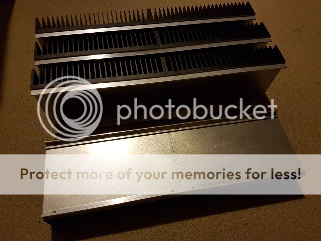
These will hopefully be the last cases I ever build. Hahaha
Next step will be to drill and tap UMS bolt patterns to all heatsinks, along with additional holes for the hockey pucks.
😉
These will hopefully be the last cases I ever build. Hahaha
Next step will be to drill and tap UMS bolt patterns to all heatsinks, along with additional holes for the hockey pucks.
😉
Congratulations as well Jama!
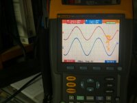
With all the fantastic graphs and details from Generg and 2 Picodumbs now you have built it! Can you please post some oscilloscope shots of square wave and frequency response.
With all the fantastic graphs and details from Generg and 2 Picodumbs now you have built it! Can you please post some oscilloscope shots of square wave and frequency response.
Yes it is race..... the cars are named Jeff, Lynn and Gerd and suddenly in a corner a car with the inscription Juan appeared..... ****!
😀😀😀
😀😀😀
Yes it is race..... the cars are named Jeff, Lynn and Gerd and suddenly in a corner a car with the inscription Juan appeared..... ****!
😀😀😀
My car was initially in the race, although it is now having engine trouble...
(not much time away from work at the moment)
My eventual plan is to use the TO-264 parts instead of the hockey pucks. According to the datasheet, they enjoy the same thermal resistance, although I am suspicious due to the difference in contact area with the heatsink. I intend to use the 40P50P and 40N90P since the higher transconductance of the P-channel part vs. the N-channel should give the negative phase second harmonic we are after.
completely right there is one more car racing I am shortsighted….. :—))
But at the moment seems he need tubes…
😀😀
But at the moment seems he need tubes…
😀😀
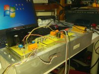
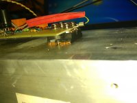
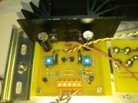
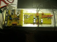
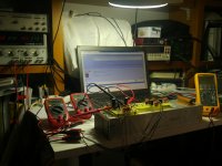
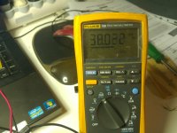
Hi all. I am not in the race.. only contribute something. I have fixed errors and later a few time looking how is thermal derive, I have adjusted for getting around 1.6A, more or less stable, without smoke or flames. It is possible do it. Attached are some photos. But I have not measure harmonics yet. Before this only want to check if works or not (smoke or flames).
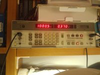
I have not get nice numbers you have obtained. Maybe because I only select ixys using vgs (I have not time for using a curve tracer and get transconductance of toshibas or ixys). My distortion level is 0.11% at 1W 8ohm and 0.36% at full power. These numbers are only numbers because I need measure for harmonics set, but not today.
Best Regards all
Attachments
Most of the distortion or lack there of, seems to come from getting the front end circuitry optimised.
The source follower output stage in isolation, already has very low distortion levels.
The source follower output stage in isolation, already has very low distortion levels.
Most of the distortion or lack there of, seems to come from getting the front end circuitry optimised.
The source follower output stage in isolation, already has very low distortion levels.
When driving the source-follower in isolation, what was the source impedance?
Driven by perfect voltage source with zero source impedance (assuming that is the default setting)
Driven by perfect voltage source with zero source impedance (assuming that is the default setting)
That explain the very low distortion measured. Try the same OS distortion measurements with the expected output impedance of the FE.
Yes that proves my point (based on telepathic communication)
I'll do that comparison when I get home to see the quantitative difference.
I'll do that comparison when I get home to see the quantitative difference.
Last edited:
Ha, ha.... only in the race of be a little more happy every day. And these little things (like hear music, build amps or speakers and specially, make good friends) do it.
Go on
Go on
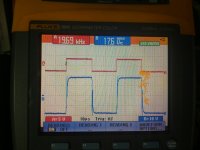
Thanks for taking the measurements Jama. I'm surprised at the rounding of the leading edge at 20KHz I would have thought the low output impedance of the front end would have negated the high input capacitance of the hockey pucks but obviously not.
We are building amplifiers here so how does it sound more importantly?
We are building amplifiers here so how does it sound more importantly?
- Home
- Amplifiers
- Pass Labs
- F4 Beast Builders