I've read were people have increased the bias on these transistors and said that there was a noticeable improvement in sound quality but it was a change from about 50ma to 100ma or 120ma. Might not need to go to 400ma.
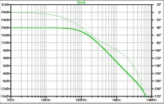
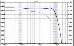
I have isolated the cause of a highly undesirable resonance in the Bode plots of the simulation, shown in the plot below. After some investigation the cause was determined to be the TL431 cascode bias generation circuits. Adding a 1k resistor between the TL431 and the cascode BJT base decreases the Q of the resonance, but does nothing to eliminate it. (Blue trace is without the 1k resistor).
I found the following papers that discuss the problem:The problem is caused by a capacitive load on the output of the TL431 and probably by the feedback loop through the cascode transidtor. I am not sure whether the problem is worth worrying about, but it seriously screws up the simulation phase and gain margin estimates. Perhaps that is good reason to use a resistor divider in place of the TL431 circuit for simulations. If cascode feedback is not being used, there is no need for the TL431 circuit. Even with cascode feedback, the PSRR and rail voltage issue issue might not be a problem.
I found the following papers that discuss the problem:The problem is caused by a capacitive load on the output of the TL431 and probably by the feedback loop through the cascode transidtor. I am not sure whether the problem is worth worrying about, but it seriously screws up the simulation phase and gain margin estimates. Perhaps that is good reason to use a resistor divider in place of the TL431 circuit for simulations. If cascode feedback is not being used, there is no need for the TL431 circuit. Even with cascode feedback, the PSRR and rail voltage issue issue might not be a problem.
Attachments

Do I understand right...
when I use CFB in the front end I should use a TL431 circuit for the cascode BJTs?
Like Pa did in the Sony II version 1 and 2?
And it is not good to use CFB with a resistor divider network?
Your last words seem to say it is possible.....
when I use CFB in the front end I should use a TL431 circuit for the cascode BJTs?
Like Pa did in the Sony II version 1 and 2?
And it is not good to use CFB with a resistor divider network?
Your last words seem to say it is possible.....
A problem with CFB and resistor dividers is rail voltage variations and noise. Low frequency rail voltage variations will change the voltage on the base of the cascode transistor, changing the current the the feedback resistors, changing the current thru the drain load resistor (pot), changing the voltage to the MOSFET gate, ... If the cascode feedback resistors have the same value and the rail voltage variations are the same (but of opposite polarity), the only effect will be equal changes to the FE MOSFET bias current, and a slight change to OLG. I have a different approach to using resistor dividers and CFB that reduces the potential problem by about a factor of 10.
:But I did it ... how can I hear the negative effects....? 😀😀
only fun!
I see that Pa returned in the one pair Sony II to the resistor network, but he also gave up the cascode feedback, so you have a strong partner!
What about your "normal" local feedback with one resistor only, besides that it possible does not lower the output impedance?
only fun!
I see that Pa returned in the one pair Sony II to the resistor network, but he also gave up the cascode feedback, so you have a strong partner!
What about your "normal" local feedback with one resistor only, besides that it possible does not lower the output impedance?
Another downside to the resistor divider is the output impedance. A 4k7/4k7 divider will have an output impedance of 2k35. With the TL431 the impedance is very low and sometimes requires an additional resistor to increase the impedance. Papa's 1k resistor might have been in accordance with figure 8 in http://www.ti.com/lit/an/slva685/slva685.pdf.
Ok now I'm getting really silly distortion results by increasing one of the cascode feedback resistors and leaving the other one alone. Distortion at 1 watt is .000093 and at 25 watts .0011.
Yes. I have 3 options:
- cascoding and TL431 bias
- cascoding and resistor divider
- no cascoding
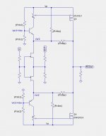
Here is a CFB scheme, using a resistor divider for the cascode transistor bias voltage, that greatly reduces the effects of rail voltage variations. It also has the benefit of increasing OLG because in the quiescent state the cascode feedback injects zero current into the cascode emitter.
Attachments
:But I did it ... how can I hear the negative effects....? 😀😀
only fun!
I see that Pa returned in the one pair Sony II to the resistor network, but he also gave up the cascode feedback, so you have a strong partner!
What about your "normal" local feedback with one resistor only, besides that it possible does not lower the output impedance?
You don't need tl431 shunt regs if the front end is preceeded by it's own decoupling RC filter to get the noise down.
You can turbo it as much as you like.
I have a serious amount of filtering in my amp so I'll probably be ok without it.
It might be fun to try feeding the front end with a cap multiplier.
I'm just focusing on getting the cases finished at this point in time.
Last edited:
That is from input to output of complete amp.Is this the complete circuit or just the front end?
- Home
- Amplifiers
- Pass Labs
- F4 Beast Builders