Drain resistance at jfets will need to drop significantly for biasing to220 laterals, combined with the lower transconductance of the to220 lateral, open loop gain will come down significantly.
I'd still try it though.
All of that is true. I haven't decided whether to use Toshiba SK2013/SJ313 and cascode feedback to get low FE output impedance and lower FE gain, or Hitachi SJ77/SK214 with no feedback in the FE. My PCBs give me both options.
I will be doing both but I will start with k2013/j313.All of that is true. I haven't decided whether to use Toshiba SK2013/SJ313 and cascode feedback to get low FE output impedance and lower FE gain, or Hitachi SJ77/SK214 with no feedback in the FE. My PCBs give me both options.
Hello brother
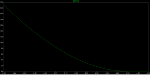
Have you managed to measure frequency response of your amp?
In simulation it is quite high (not a bad thing) but to bring it down to a sensible level I had to add extra resistance at the gates of k2013/j313.
If you can do that measurement that would confirm weather the simulation is reasonably close.
Generg, there is a pspice model for IXTK40P50P which is a T0-264 part but the datasheet looks the same as the sot227 part. There is also pspice model for the part Ihquam is using, the IXFN44N80Q3
IXYS Website > Part Search Results
IXYS Website > Part Search Results
IXYS Website > Part Search Results
IXYS Website > Part Search Results
From memory, I think Generg and I tested that model and there were serious errors with it, so I decided to make my own simple spice models from scratch.
I just found a simulation using these parts that I did last summer when I first started using LTspice. I used the ba-3 FE. It seems to simulate ok. What are the problems Picodumbs do you remember?
What is the best way to measure this?what's difference in Rdson between chosen N and P brothers ?
I set Vgs=10V then apply a small voltage say 1V Vds? It might exceed the current output of my lab power supply ie 3A
What temperature do you want this measured at?
Last edited:
I just found a simulation using these parts that I did last summer when I first started using LTspice. I used the ba-3 FE. It seems to simulate ok. What are the problems Picodumbs do you remember?
I remember doing a curve of Id vs Vgs and it spat out junk.
If you can repeat that and see if it operates correctly then I'll go back and check it again.
What is the best way to measure this?
I set Vgs=10V then apply a small voltage say 1V Vds? It might exceed the current output of my lab power supply ie 3A
What temperature do you want this measured at?
which else than working temp - say 60C on heatsink near to part
what I meant - instead of TL431 and NTC gadget , one can introduce 0R1 in appropriate rail ( thus most probably equalizing difference in Rdson between two sexes) and going to set Iq trough appropriate measuring of voltage drop across mentioned 0R1
that way , OS could be placed on much broader range of heatsinks ( count on normal Greedy Boyz behavior)
so , 0R1 , OP , one precision zenner , few resistors and one optocoupler , that's all needed for flawless bias operation
I believe that idea is recently covered around (lhquam ?) , but I didn't follow it thoroughly , just because it was in context of M2 , and I wasn't interested in bettering it
most probably still not interested in bettering M2
hey - but it's wakoo idea - input buffer , autoformer - interstage buffer - puck follower

mini F5T/BA3FE tweaked as FE ..... sorta boring ....... for me - exact biasing scheme Pa is using here , is that jewel worth looking for , in XA25
OK , exact pucks combo , too ...... believing that he did his own homework thoroughly , as always is the case ..........
Ok, I made a mistake, I only used one of them. I used the IXFK44N50 and IXTK40P50P.
Could you check IXTK40P50P. Do Id vs Vgs and let me know.
which else than working temp - say 60C on heatsink near to part
what I meant - instead of TL431 and NTC gadget , one can introduce 0R1 in appropriate rail ( thus most probably equalizing difference in Rdson between two sexes) and going to set Iq trough appropriate measuring of voltage drop across mentioned 0R1
that way , OS could be placed on much broader range of heatsinks ( count on normal Greedy Boyz behavior)
so , 0R1 , OP , one precision zenner , few resistors and one optocoupler , that's all needed for flawless bias operation
I believe that idea is recently covered around (lhquam ?) , but I didn't follow it thoroughly , just because it was in context of M2 , and I wasn't interested in bettering it
most probably still not interested in bettering M2
hey - but it's wakoo idea - input buffer , autoformer - interstage buffer - puck follower
mini F5T/BA3FE tweaked as FE ..... sorta boring ....... for me - exact biasing scheme Pa is using here , is that jewel worth looking for , in XA25
OK , exact pucks combo , too ...... believing that he did his own homework thoroughly , as always is the case ..........
Existing biasing scheme works like glue, nothing to fix at all.
Certainly there are other ways to the skin the cat though.
yup
and as I said before - I'm not exactly looking for skinned cat ...... I'm more about ways to do it
and as I said before - I'm not exactly looking for skinned cat ...... I'm more about ways to do it
The passheadphone diy amp uses an opto. Just playing around in ltspice I used the irfp240 and complement but I put two op amps, one between cathode and source resistor and the other on the anode and other source resistor. I used .01 ohm resistors and set the gain for 40 on the op amps for 1.4 amps bias. I had to put a cap to ground on the output of the op amps to lower the ac. It did seem to work.
The passheadphone diy amp uses an opto. Just playing around in ltspice I used the irfp240 and complement but I put two op amps, one between cathode and source resistor and the other on the anode and other source resistor. I used .01 ohm resistors and set the gain for 40 on the op amps for 1.4 amps bias. I had to put a cap to ground on the output of the op amps to lower the ac. It did seem to work.
That is not really enough though, I want to see if they produce curves that are representative of the raw part or not.
yup
and as I said before - I'm not exactly looking for skinned cat ...... I'm more about ways to do it
I need to finish this amp first. Once complete I will be happy to go back and entertain some of these other fun ideas. It is always fun seeing what tricks Papa has up his sleeve.
At the moment the bias circuit works perfectly (well good enough). I will video it's behavior.
- Home
- Amplifiers
- Pass Labs
- F4 Beast Builders