OK Fellow Dumb Bastards.
The cat is gonna be out of the bag sooner or later, it may as well be sooner.
I'm not gonna give ya resistor values, I'm a believer in using ya dumb brain not copying.
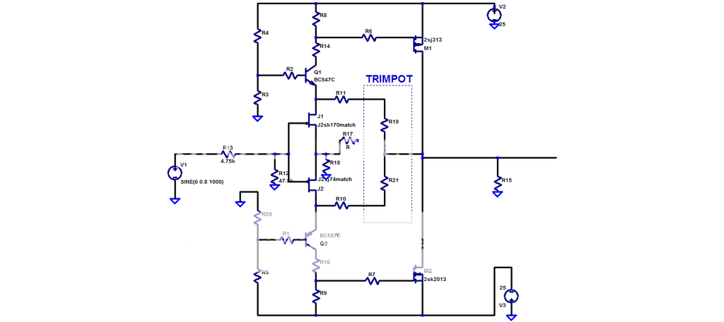
Here is my circuit.
I may change from this before it's completed though I'm easily bored.
The cat is gonna be out of the bag sooner or later, it may as well be sooner.
I'm not gonna give ya resistor values, I'm a believer in using ya dumb brain not copying.
Here is my circuit.
I may change from this before it's completed though I'm easily bored.
You can cascode if you want, but the main reason papa did so in Sony is because the sony devices produce triode curves.
The IXYS devices are strongly pentode and capacitance isn't that high to lose sleep over, so adding cascode is really a personal choice not a requirement.
With the "correct" choice of IXYS devices it looks like cascoding of the output fets might only reduce input capacitance by about 50% with an 8R load, even less with lower load impedances.
Last edited:
Yeah. It's not really worth the extra parts count.
Consider the capacitance in the output stage of say the XA100.8 and all of a sudden 10nF per device doesn't seem such a large figure at all.
Consider the capacitance in the output stage of say the XA100.8 and all of a sudden 10nF per device doesn't seem such a large figure at all.
Last edited:
Keep going brother. 🙂
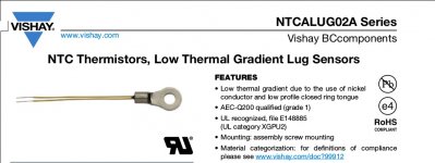
Is this similar to the type of thermistor you are bolting to the heatsink?
http://www.vishay.com/docs/29092/ntcalug.pdf
Is this similar to the type of thermistor you are bolting to the heatsink?
http://www.vishay.com/docs/29092/ntcalug.pdf
Attachments
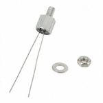
I have used these: Mouser part #594-NTCALUG02A472F http://www.mouser.com/ProductDetail...GAEpiMZZMuBd0%2bwiCVS29cFeDjED7IBg/nN8NMR3zg=
Attachments
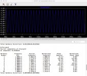
yeah I got the 0.00X at least and first in Spice even uncascoded......😀😀
I remembered that the original XA25 is said to have 20dB gain.
I always worked with 26dB gain, coming from XA30.5.
So I stayed for the gain resistor with a value of around 110R and choose a lower value for the feedback resistor, around 1k2.
Now with 20dB gain only,
it is no more problem to get for 1W at 8Ohm the 0.00x value.
Let us see next days what happens in reality.....🙂
Not to speak of the work to get possible neg k2 phase or use of CFB.
All in all playing is really fun.
More awful is of course the part to hear what really sounds better.... I tend to avoid this part and admire Nelson and his people doing this in a great scale.
Attachments
yeah I got the 0.00X at least and first in Spice even uncascoded......😀😀
.
About bloody time you dumb bastard. Hahahahahaha
🙂
You were making me sound like a broken record. "you don't need cascode,,,,,,you don't need cascode...... you don;t need cascode"
a million bloody times.
Hahahahahaha
Good to see you happy.
Last edited:
you did not tell me how to do it, so it took me a time to find it out....!
Brocken record? long time ago this happened in my house.....
😀😀😀
Brocken record? long time ago this happened in my house.....
😀😀😀
Not to speak of the work to get possible neg k2 phase or use of CFB.
Information is all in first post, but many ways to skin the cat.
Last edited:
you did not tell me how to do it, so it took me a time to find it out....!
Brocken record? long time ago this happened in my house.....
😀😀😀
Excellent work brother.

I understand that the dissemination of Ideas over geographic obstacles can be sloooow (lightly studied the phenomena at Uni)
... but ~40 years for Monty Python sketches to arrive in Ancient Batsch...
Is a surprisingly long time 😉
... but ~40 years for Monty Python sketches to arrive in Ancient Batsch...
Is a surprisingly long time 😉
Not to speak of the work to get possible neg k2 phase or use of CFB.
All in all playing is really fun.
Hello brother
As an alternative to careful part selection, and other more technical techniques to achieve your goal, why not do something dumber.
If you add 0.05 Ohms (50 mOhms) to the source of the N Channel Mosfet it will give you the effect you want. I don't think this small amount of degeneration would hurt the natural bias scaling of the output stage. For the cost of a dollar it's worth a try.
Even 25 mOhms will do the trick (2 in parallel).
I might play with this myself. I like dumb ideas. Hahahaha
https://www.digikey.com.au/product-...ctronics-inc/MPR3JB50L0/MPR3JB50L0-ND/1646064
Last edited:
Yes, i will try it.
First i have to train me again to measure the residual with Virtins software to know Rallye what k2 Phase comes out.
Lhquam already told that you have to overwhelm a lot of pos k2 phase to come in the neg region.
By the way I can live with pos phase as well, sometimes I like it even more.
First i have to train me again to measure the residual with Virtins software to know Rallye what k2 Phase comes out.
Lhquam already told that you have to overwhelm a lot of pos k2 phase to come in the neg region.
By the way I can live with pos phase as well, sometimes I like it even more.
- Home
- Amplifiers
- Pass Labs
- F4 Beast Builders