Hey all,
So a while ago I had an issue with an f3 amp, which turned out to be a dodgy q5 in the right channel. I now have a dead left channel.
There is no current draw when I attach it to a bench, and I get the following readings on q5 :
46v on the drain
45.4v on the gate and source (ish)
Q3 gives me :
45.4v on the source
<1v on the other pins
The fact that it's not drawing current has me stumped.
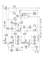
The gate of Q5 needs to be pulled down more. Check the voltage between R19 and C5. If it's also 45.4-ish that would suggest a cold joint on C5 or a failed D1.
Reflowed. No difference. Testing the point between r19 and c5 is giving 45.4 (ish).
Tomorrow I'll redo d1
Tomorrow I'll redo d1
OK.
Replaced D1, and also resoldered Q3 (which looked off). Still no current draw, but the voltages are now 42V on the gate and source of Q5.
I was playing around with P1 and P2 before I replaced the diode, so will start bringing those back up to where they should be.
Replaced D1, and also resoldered Q3 (which looked off). Still no current draw, but the voltages are now 42V on the gate and source of Q5.
I was playing around with P1 and P2 before I replaced the diode, so will start bringing those back up to where they should be.
I've also got a few spare jfets if you/we need them - I got the last of the GBs from Mr Rollins a few years ago and they're group matched for that current use.
Sounds like the diode was indeed shorted.
Having the wrong bias set on the JFET could result in no current draw, so resetting P1 and P2 may be all that's needed.
Having the wrong bias set on the JFET could result in no current draw, so resetting P1 and P2 may be all that's needed.
Should the pots start at the halfway point?
Have no idea. I do remember it being a bit tricky, but I don't remember much more than that.
Probably doesn’t matter too much since you Have a CCS in the circuit which should protect the device.
Middle is probably a decent starting point.
I don’t have the circuit in front of my eyes.
Middle is probably a decent starting point.
I don’t have the circuit in front of my eyes.
Closer!
The amp is pulling the 1.6amps, but I'm getting about 37v at the source of q5, and the power seems to ramp up quickly, rather than slowly.
But other points are good - 3.5v at the drain of q1.
The amp is pulling the 1.6amps, but I'm getting about 37v at the source of q5, and the power seems to ramp up quickly, rather than slowly.
But other points are good - 3.5v at the drain of q1.
I just replaced d1, so I'll check and/or replace those other components. What should I look out for? Cold joints? Shorts?
So q5 is still good then given those measurements?
I really appreciate everyone's help by the way - you're all excellent!
So q5 is still good then given those measurements?
I really appreciate everyone's help by the way - you're all excellent!
Check R19 is actually 47.5k and not some dumb value like 4.75k
Check solder joint of C5 and if they look good, then consider replacing it. It could be a bad capacitor.
Check solder joint of C5 and if they look good, then consider replacing it. It could be a bad capacitor.
- Home
- Amplifiers
- Pass Labs
- F3 Builders Thread
