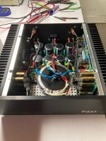
Why yes Virginia, you can stuff an F3 clone into a 3U Mini Dissipante (but should you?)
So, at the end of last year Modushop had a "cyber Monday" sale, and I couldn't help but buy a chassis even though I didn't yet have an amp in mind for it. I've long liked the form factor of the 2U Mini Dissipante case that the ACA comes in, so I went for one size up, a 3U, 300mm long, even though the heat sinks were too small to take the standard UMS drilling pattern. To save costs and improve optionality, both the back plate and the front plate were ordered un-drilled as well, just black anodized. It would be a while yet before I had access to a machine shop and the bravery to drill, tap, mill, and engrave this sleek and fancy little chassis the way I envisioned.
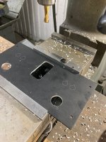
Fast forward a few months and things were coming together. A friend helped me mark out the portion of the UMS heatsink pattern that I needed using a CNC laser, and also helped tap and drill, and I taught myself how to laser engrave something more complex, the logos I wanted on the face plate. Lastly, I got brave and milled out the back plate to accept all the sockets & plugs.
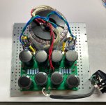
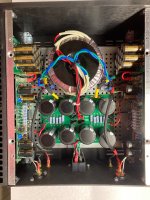
This chassis is a super tight fit. The PSU, with a fortuitously tall and narrow 300VAC Antek trafo & @rhthatcher's snubber rectifier boards, barely fits on the baseplate. I needed a special artisanal Japanese right-angle screwdriver to affix the front plate, and a very clear order of assembly, to include pre-attachment of the quick-disconnect cables, which I stumbled across only through trial and error. But it came (and is coming) together.
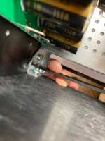
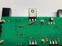
But what of the heat, you ask? My particular F3 clone, for reasons that remain somewhat nebulous to me, is under-biased relative to it's First Watt brethren- the Vds across the LU1014D's is only about 2V, the bias is 1.4A, so the LU's themselves are dissipating about 3W. A bench supply confirmed 1.45A of current draw at 46V, for ~69W of dissipation per channel. The Mini Dissipante 3U 300mm heat sinks are rated at 0.40C/W, which works out to a max of about 30C above ambient. High, yes, but I've been running these for a couple hours now and they're no hotter to the touch than an ACA, at least with an open lid. That heat seems to be concentrated in the area of Q2. I'm fine with this as IRFP240s are tough as nails.
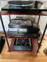
This amp remains my favorite. With my Seas A26 speakers, which are probably something higher than 8 ohms nominal, the midrange is golden, the bass totally in control. This system excels at jazz and especially vinyl jazz, which to me has become a gold standard and means this system does a lot of things right.
So, at the end of last year Modushop had a "cyber Monday" sale, and I couldn't help but buy a chassis even though I didn't yet have an amp in mind for it. I've long liked the form factor of the 2U Mini Dissipante case that the ACA comes in, so I went for one size up, a 3U, 300mm long, even though the heat sinks were too small to take the standard UMS drilling pattern. To save costs and improve optionality, both the back plate and the front plate were ordered un-drilled as well, just black anodized. It would be a while yet before I had access to a machine shop and the bravery to drill, tap, mill, and engrave this sleek and fancy little chassis the way I envisioned.
Fast forward a few months and things were coming together. A friend helped me mark out the portion of the UMS heatsink pattern that I needed using a CNC laser, and also helped tap and drill, and I taught myself how to laser engrave something more complex, the logos I wanted on the face plate. Lastly, I got brave and milled out the back plate to accept all the sockets & plugs.
This chassis is a super tight fit. The PSU, with a fortuitously tall and narrow 300VAC Antek trafo & @rhthatcher's snubber rectifier boards, barely fits on the baseplate. I needed a special artisanal Japanese right-angle screwdriver to affix the front plate, and a very clear order of assembly, to include pre-attachment of the quick-disconnect cables, which I stumbled across only through trial and error. But it came (and is coming) together.
But what of the heat, you ask? My particular F3 clone, for reasons that remain somewhat nebulous to me, is under-biased relative to it's First Watt brethren- the Vds across the LU1014D's is only about 2V, the bias is 1.4A, so the LU's themselves are dissipating about 3W. A bench supply confirmed 1.45A of current draw at 46V, for ~69W of dissipation per channel. The Mini Dissipante 3U 300mm heat sinks are rated at 0.40C/W, which works out to a max of about 30C above ambient. High, yes, but I've been running these for a couple hours now and they're no hotter to the touch than an ACA, at least with an open lid. That heat seems to be concentrated in the area of Q2. I'm fine with this as IRFP240s are tough as nails.
This amp remains my favorite. With my Seas A26 speakers, which are probably something higher than 8 ohms nominal, the midrange is golden, the bass totally in control. This system excels at jazz and especially vinyl jazz, which to me has become a gold standard and means this system does a lot of things right.
Attachments


The Nichicon's will be fine.Hi,
I ordered some Nichicon UKA (P/N: UKA1H221MPD) for C2-C7 and Elna SILMIC II (P/N: RFS-35V221MI6#5) for C10. When I received the parts from mouser, I noticed that those Nichicon UKA were only half of the size of Elna SILMIC II. Initially I was surprised that why a 50V cap is smaller than a 35V cap with same number of uF. After checking the ripple current, I noticed that the one in Nichicon is only 330mA verse 550mA in Elna. Any harm if I use those Nichicon UKA for C2-C7??
In fact, that combination is exactly what I used.
My F3 is oscillating. Little help?
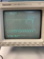
If I power up my F3 clone with shorted inputs & 8R 20W non-inductive resistors on the outputs, scope probes on the negative speaker poles show the traces in the first image. The right channel (Ch1, top) looks to be about 600mV from the bottom spike to the top peak (the voltage swing varies over time from 300-600mV), and is in the neighborhood of 85kHz. The left channel (Ch2, bottom) is also about 600mV p-p but is in the neighborhood of 300kHz. For my sanity I'm assuming this is the AC from the Aleph CCS. Why the frequency differs channel to channel, idk, they're both set to ~20V. But I have weird delayed pops from the right (slow) channel on power up so maybe this is related.
If I apply an ~80Hz, ~2V p-p signal (from a Moog analog synthesizer lol) to the inputs, something disturbing happens. From power on of the amp, through to power off, we can see first the amp come online, faithfully amplifying the sine wave, then a little while later, massive amounts of oscillation appear, lasting until the amp is powered down. Note again this is with a 'non-inductive', 8R 20W power resistor across the outputs.
The google drive links to these videos are below. The right channel goes nuts quicker than the left:
Left channel: https://drive.google.com/file/d/1VprerqL29UkM6z5KVgbHXhLdvT6sj799/view?usp=sharing
Right channel: https://drive.google.com/file/d/1kY5Yv2irOMxUe001W66syVueYkCyCzLB/view?usp=sharing
I'd like to know how to stop this. I'm tempted to put an RC network composed of an 0.1uF film cap and a 14R7 1W resistor across the speaker outputs because this is what I have laying around (in proper RC this is a low pass of about 108KHz) but if there's a more intelligent way to squelch this I'd love to hear it.
Attachments
show more detailed pics of your build, channel pcbs
be sure that gate resistors are really close to gates
increase them, as first measure
be sure that gate resistors are really close to gates
increase them, as first measure
There are no gate stoppers for the LUs in the F3 design ZM, and especially so for LUs mounted direct to these PCBs, no option for adding them, unless I lift a leg. If I had used the xrk971 adapters for them then I would have had the option of adding 100R gate stoppers. I may yet do so if I give up on this mounting approach, but it'll have to be with fresh LUs as these things can't take the heat.show pics of your build
be sure that gate resistors are really close to gates
increase them, as first measure
Edit: well, maybe not. I could try adding 100R or 220R to the gates. What say you?
Attachments

Last edited:
OK
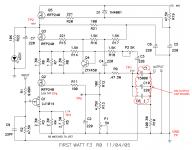
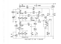
according to schm you posted - you can freely increase gate stoppers for Q5 and Q2 , even to 510R, without penalty
Q3, you can increase it to 390R without penalty
now, there is gate stopper for LU gate , and that's exactly R1, being 9K1
it was needed that R1 is close to LU gate, whoever made that pcb
of course, if it isn't - you can hopefully cut the trace near LU gate, and install at least 100R there, as dedicated gate resistor
Thx ZM, much appreciated. Thinkin I might lift a leg and add a 100R to the LU gate, but it's nice to know that increasing R1 won't mess with the voltage division or Zin or feedback too bad.OK
according to schm you posted - you can freely increase gate stoppers for Q5 and Q2 , even to 510R, without penalty
Q3, you can increase it to 390R without penalty
now, there is gate stopper for LU gate , and that's exactly R1, being 9K1
it was needed that R1 is close to LU gate, whoever made that pcb
of course, if it isn't - you can hopefully cut the trace near LU gate, and install at least 100R there, as dedicated gate resistor
well, not actually increasing 1 per se
adding 100R (or something as that) after node formed with R1 with R2, will not change feedback ratio
again, if you can cut the trace near LU gate, that would be best solution for adding missing resistor
LU's tiny pins are fragile, and doing everything else than messing with them , is advisable
adding 100R (or something as that) after node formed with R1 with R2, will not change feedback ratio
again, if you can cut the trace near LU gate, that would be best solution for adding missing resistor
LU's tiny pins are fragile, and doing everything else than messing with them , is advisable
Lift a leg
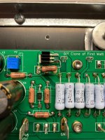
So I did the thing, 100R gate stoppers on the LUs now. Had to remount one LU completely to an XRK board as the drain didn't have good conduction to the main amp PCB. To my delight it survived the resoldering & if anything it has a higher Id now than before. I was able to dial the Vgs >2V on that side now too which makes me happy (Lch, 2.36V, Rch 2.4V!). There is still that odd high frequency sine on both channels (~133kHz Lch, ~91kHz Rch) into 8R with inputs shorted that doesn't change a whole lot with tweaks to P1 or P2. Also weird weird things still happen when I feed it with an 80Hz sine wave from my moog synth, and there's the delayed start-up pop on the right channel that I am baffled by. I called it good, put the lid on & am listening to it now. It's smooth and warm compared to my Aleph 30. Love 'em both.
So I did the thing, 100R gate stoppers on the LUs now. Had to remount one LU completely to an XRK board as the drain didn't have good conduction to the main amp PCB. To my delight it survived the resoldering & if anything it has a higher Id now than before. I was able to dial the Vgs >2V on that side now too which makes me happy (Lch, 2.36V, Rch 2.4V!). There is still that odd high frequency sine on both channels (~133kHz Lch, ~91kHz Rch) into 8R with inputs shorted that doesn't change a whole lot with tweaks to P1 or P2. Also weird weird things still happen when I feed it with an 80Hz sine wave from my moog synth, and there's the delayed start-up pop on the right channel that I am baffled by. I called it good, put the lid on & am listening to it now. It's smooth and warm compared to my Aleph 30. Love 'em both.
Attachments
well, tricks of trade
if that is the case, cut trace near mosfet.....mount gate resistor there
if that is the case, cut trace near mosfet.....mount gate resistor there
Good catch Jeff. It looks like the gate resistors are some distance away:
https://www.diyaudio.com/community/attachments/amp-and-coupling-cap-board-png.961112/
https://www.diyaudio.com/community/attachments/amp-and-coupling-cap-board-png.961112/

Now lift the other leg
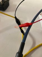
To recap, my F3 clone was oscillating in both channels, even after adding 100R gate stoppers to the LUs. Oscillation was first detected by oscilloscope trace and confirmed using the device of the circuit below (except using 5nF instead of 4.7nF), which when placed across the speaker terminals lights the LED if any oscillation of > 1V above approximately 20kHz is present. In contrast my Aleph 30 didn't light the LED under similar conditions (same inputs and preamp, same speaker cables and speakers). With such evidence in hand I elected to loosely pursue the remedies of Zen Mod, described above, eg increasing the gate stopper values: "Q2, Q5 to 510R okay, Q3 to 390R okay".
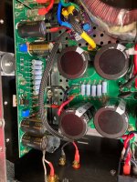
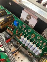
I replaced the gate stoppers on Q2 and Q3 with 396R resistors. For the LH channel, I tied the new gate resistor directly to the gate of Q2 as shown in the picture, but simply replaced R15 in it's original holes with the higher value, as the trace distance to the gate of Q3 on the LH side was about the same as it would be if I dead-bugged the new resistor value to the gate. For the RH channel, both gate traces were longer, so I chose to dead-bug them both (sorry, I forgot to take a picture). With music playing the LH channel is now clean but the RH channel still oscillates, lighting the LED dimly. That said, the annoying delayed turn on and sudden turn off pop that was present only in the RH channel appears to be gone, so progress has been made.
What to try next? For RH only, should I modify Q5's gate stopper too? Do I go to 510R for Q2 and/or Q5? Try undoing the R15 dead-bug on the RH and mount it through hole? I'm looking for ideas. Thank you for reading this far.
To recap, my F3 clone was oscillating in both channels, even after adding 100R gate stoppers to the LUs. Oscillation was first detected by oscilloscope trace and confirmed using the device of the circuit below (except using 5nF instead of 4.7nF), which when placed across the speaker terminals lights the LED if any oscillation of > 1V above approximately 20kHz is present. In contrast my Aleph 30 didn't light the LED under similar conditions (same inputs and preamp, same speaker cables and speakers). With such evidence in hand I elected to loosely pursue the remedies of Zen Mod, described above, eg increasing the gate stopper values: "Q2, Q5 to 510R okay, Q3 to 390R okay".
I replaced the gate stoppers on Q2 and Q3 with 396R resistors. For the LH channel, I tied the new gate resistor directly to the gate of Q2 as shown in the picture, but simply replaced R15 in it's original holes with the higher value, as the trace distance to the gate of Q3 on the LH side was about the same as it would be if I dead-bugged the new resistor value to the gate. For the RH channel, both gate traces were longer, so I chose to dead-bug them both (sorry, I forgot to take a picture). With music playing the LH channel is now clean but the RH channel still oscillates, lighting the LED dimly. That said, the annoying delayed turn on and sudden turn off pop that was present only in the RH channel appears to be gone, so progress has been made.
What to try next? For RH only, should I modify Q5's gate stopper too? Do I go to 510R for Q2 and/or Q5? Try undoing the R15 dead-bug on the RH and mount it through hole? I'm looking for ideas. Thank you for reading this far.
Attachments

Well Mighty ZM, that did it. No more oscillation on that channel. The LED don't light and the mains hum headphone tester I got from @rhthatcher don't screech anymore, neither. Thank you very, very much.you can try a trick from Alephs
1nF cap , B to C at Q4
It's a little hard to be happy on such a somber day here in the US though.
Attachments


tell us more about different Lii
- Home
- Amplifiers
- Pass Labs
- F3 Builders Thread