problem with switchers is - when you want to use two single rail ones in series, to get bipolar supply - first you need to get rid of any connection of rails and switcher cases and - second, they must have so-so syncronous startup, to avoid possible thumps, burps or even gray smoke from amp itself (depending of amp construction of course, and how fast biasing process is)
so, single rail amps are no brainer
dual rail amps - best to go with dedicated constructed switchers for purpose
can't exactly remember in which threads I did read of them, nor exact produce; reason - I'm not interested exactly, getting linear supply good enough is still easier and even less costly, in my neck of wood
I was thinking of the industrial 48v greater than 200 watt types like this, housed in a small separate chassis, cost is double the "laptop" supplies.
https://www.meanwellusa.com/upload/pdf/HRPG-300/HRPG-300-spec.pdf
My problem is I am a hobbyist with little/no electrical design skills, and trying to take the examples of the 36 volt filter / thump reducer boards and transitioning to 46-48 volts is beyond my skills.
https://www.meanwellusa.com/upload/pdf/HRPG-300/HRPG-300-spec.pdf
My problem is I am a hobbyist with little/no electrical design skills, and trying to take the examples of the 36 volt filter / thump reducer boards and transitioning to 46-48 volts is beyond my skills.

Hi,
I’m wondering how big a Switching power supply would have to be so it’s reliable. Let’s see, 48Vdc, bias of 1.65A that’s 80W of constant power so 160W if powering 2 channels.(if the power factor of the supply is close to 1)
Would a 600W for stereo or 300W per channel be ok ?
People tend to use much more powerful supply when using switching mode type but no clue how much more...factor of 2,3...
If anyone has any idea based on experience please let me know. Don’t feel like buying a 800W supply if a 400W does the job.
Thanks
Eric
yes....
Would a 600W for stereo or 300W per channel be ok ?
.....
Hello,
I have several questions about the parts of F3.
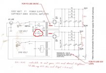
1. What is the purpose of the capacitor(0.0033uF) between the L and N of the main power? Is it necessary to add that cap between L and N?
2. What should be the voltage of C9(33pF)? Is it necessary to choose 300V or above??
3. What should be the voltage of C8? Is 35V good enough for this case?
I have several questions about the parts of F3.
1. What is the purpose of the capacitor(0.0033uF) between the L and N of the main power? Is it necessary to add that cap between L and N?
2. What should be the voltage of C9(33pF)? Is it necessary to choose 300V or above??
3. What should be the voltage of C8? Is 35V good enough for this case?
1. It filters out noise in the AC power. The amplifier will still work without it but why omit it? It is inexpensive and beneficial.
2. 300V is not necessary. The maximum voltage is from the maximum music output from the amplifier as part of the feedback circuit. The specs say the maximum unclipped voltage output is +/-13V. Allowing a bit more for clipping, 20V would be enough with room to spare. 300V is probably because mica capacitors used in this position are typically available mainly in high voltages.
3. 35V is enough. The voltage at this location is around 21V.

Hi all,
I'm testing my pal Mauro's build on 300mm Deluxe cabinet. Goop on LU PCB adapters and pads on MOSFETs.
After 20min I have those temperatures on transistor bodies:
Q1: 40°C
Q2: 63°C
Q3: 50°C
Q5: 40°C
I'm a bit worried about Q2: is it normal, or better go for mica+goop? The amp is very quiet.
Thanks in advance

if nomenclature is per original schmtc, Q2 and Q3 are having not exactly equal but similar/close dissipation, thus their temperature needs to be similar
if by "pads" you think of common silicone pads squishy thingies - yes - mica+goop is enormously better than that
those are good up to, say. 10-ishW of dissipation per TO247
more, use better ones - mica, Alumina, Keratherm 86/82
if by "pads" you think of common silicone pads squishy thingies - yes - mica+goop is enormously better than that
those are good up to, say. 10-ishW of dissipation per TO247
more, use better ones - mica, Alumina, Keratherm 86/82
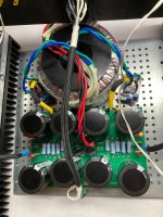
I'm in the process of swapping the toroids and rectifiers on my F3 and one of the thermistors, the one that shunts across the two neutral (black) legs of the primary, is getting very hot (60-70c) (circled red in schematic). The others, including the one that shunts the line side (red) legs, all read in the 20's to low 30c. A picture of the PSU is below.
Each primary reads 2R5 red-to-black. I can't read any resistance value (it's an open circuit) black-to-black or red-to-red. I haven't measured the secondaries.
The trafo with this behavior is a 300VA Antek AN-3236 (unshielded). This differs from the earlier setup in that each of these secondaries is 36VAC. A single secondary goes to each new bridge rectifier, which has snubber circuitry with values determined using a Quasimodo. Previously I was using two 200VA Antek AS-2218's (shielded), with the 18VAC dual secondaries on each trafo wired in series to give 36VAC. These went to un-snubbed discrete Schottky rectifiers. Each half of the PSU had it's own trafo. I don't recall checking the thermistor temps in this earlier setup.
One next step is to go back to a single one of the 200VA trafos and see if the thermistor gets hot again. Obviously I changed a lot of things simultaneously and may have to systematically swap them out one by one but I was hoping to get some ideas first. Hot thermistors are kinda scary.
Edit: is it because I'm testing at low volume and the trafo is just passing a ton of waste current?
Attachments
Last edited:
mains located NTC is seeing mains current though, so it is normal to get hot
though, if you have 2pcs of mains NTCs ( dual primary practically in parallel for 115Vac operation), it's logical that both are of same temperature
just in case ( thing I need to keep reminding my self!) - never touch them while amp is connected to mains
though, if you have 2pcs of mains NTCs ( dual primary practically in parallel for 115Vac operation), it's logical that both are of same temperature
just in case ( thing I need to keep reminding my self!) - never touch them while amp is connected to mains
I used an infrared temperature gun-thing to detect the high temps initially but did confirm by touching the CL-60 directly, which agree was dumb. The opposite side of the disk didn't read as hot by temp gun but I couldn't touch it as it's mounted nearly against one of the PSU capacitors. And yes I would expect similar temperatures on the line-side thermistor as well, even though that's not what I got.
Also I realized I can't test just one of the 200VAC trafos as the secondaries are the wrong voltage for that.
Also I realized I can't test just one of the 200VAC trafos as the secondaries are the wrong voltage for that.
Infrared thermometers may give inaccurate readings in some situations. If you have another thermometer such as a cooking thermometer, give that a try.
I suggest bending the CL-60 away from the capacitor. The heat added to the capacitor is not good for its health.
Another check would be to check that both sides of the power supply is drawing the same current. You can do that by measuring the resistance across one of the power supply 0.47R resistors at each side of the power supply. The voltage at each side should be the same if the current at each side is the same.
Hi,
I ordered some Nichicon UKA (P/N: UKA1H221MPD) for C2-C7 and Elna SILMIC II (P/N: RFS-35V221MI6#5) for C10. When I received the parts from mouser, I noticed that those Nichicon UKA were only half of the size of Elna SILMIC II. Initially I was surprised that why a 50V cap is smaller than a 35V cap with same number of uF. After checking the ripple current, I noticed that the one in Nichicon is only 330mA verse 550mA in Elna. Any harm if I use those Nichicon UKA for C2-C7??
I ordered some Nichicon UKA (P/N: UKA1H221MPD) for C2-C7 and Elna SILMIC II (P/N: RFS-35V221MI6#5) for C10. When I received the parts from mouser, I noticed that those Nichicon UKA were only half of the size of Elna SILMIC II. Initially I was surprised that why a 50V cap is smaller than a 35V cap with same number of uF. After checking the ripple current, I noticed that the one in Nichicon is only 330mA verse 550mA in Elna. Any harm if I use those Nichicon UKA for C2-C7??
Thanks for the advice, I did bend the CL-60's a bit. I repositioned the trafo, cleaned up it's leads and tried again, letting it run in air for an hour or so. I didn't measure anything much hotter than 60c from the CL-60's which is cooler than some of the bias resistors get. I guess this is fine. : insert thumbs up in burning house meme here:Infrared thermometers may give inaccurate readings in some situations. If you have another thermometer such as a cooking thermometer, give that a try.
I suggest bending the CL-60 away from the capacitor. The heat added to the capacitor is not good for its health.
Another check would be to check that both sides of the power supply is drawing the same current. You can do that by measuring the resistance across one of the power supply 0.47R resistors at each side of the power supply. The voltage at each side should be the same if the current at each side is the same.
- Home
- Amplifiers
- Pass Labs
- F3 Builders Thread