Hey Peter,
Just to let you know, I'm going to abduct you, lock you into my workshop for a week or 2 and feed you sheet alu and food. Let you recase all my audio projects then send you home.
Deal? ok?😀
Fran
Just to let you know, I'm going to abduct you, lock you into my workshop for a week or 2 and feed you sheet alu and food. Let you recase all my audio projects then send you home.
Deal? ok?😀
Fran
As usual, magnificent execution
My imagination cannot conceive of a better way to package an amplifier. Of course, my imagination would have never come up with THAT, but once seen one knows that THIS is how it should be done if only one had the skills.
Mr. Pass has an unique understanding of electronic circuits but Peter Daniel has this same level of conception for execution of the circuit into "productum". I suspect even Mr. Pass took a longing look at your work.
I guess the pads looked like some kind of metal intermediary between
output device and heatsink. Your other photos make this plain to me now. Thanks for the clarification.
Beautiful.
Rick McInnis
Hi Peter,
Everything has been worked out regarding de PCBs, a fellow member of the forum has some spares that he's just sold me.
Now I need to start looking for parts and such.
Do you have a part # for the heat sinks pictured above in posts 656 and 661? Will those work for the F3? One could hold Q1/Q2 and Q3/Q5 in the other. PCB would go in the middle and this could yield a neat monoblock configuration.
Looking at the PCBs they look like both audio and PS boards can be sawn in half to make this happen. What would be the best way to saw those boards apart - hacksaw, dremel?
Take care,
Luis
Hello everyone,
I'm just starting to collect parts for an F3 build and looking at the service manual I got some questions.
Please excuse me if these have been answered before and if these sound too basic, it's my first build in more than 10 years and the fist at high-end hi-fi.
- do I have to get matched JFETs and MOSFETs?
- in the schematic one can read "R5 matched to JFET" - what does this mean?
- I can't find R13 on the PCB, should I just increase P1 to 10K?
- what are you guys using for C1 / C8 / C10 coupling caps? maybe a BlackGate for C10? which one - FK is only 25V while the standard can be found in 50V and 100V? PIO or other fancy film cap for C8?
- all resistor can be 1/4W other than the ones marked 3W?
- I see lot's of 220uF - what are you guys using? Nichicon KZ 100V?
While using quality components sounds like the ticket for good performance I think that focus should be given to components in the signal path... what parts should I be paying more attention?
Thanks in advance,
Luis
luis.martins said:Hello everyone,
I'm just starting to collect parts for an F3 build and looking at the service manual I got some questions.
Please excuse me if these have been answered before and if these sound too basic, it's my first build in more than 10 years and the fist at high-end hi-fi.
- do I have to get matched JFETs and MOSFETs?
- in the schematic one can read "R5 matched to JFET" - what does this mean?
- I can't find R13 on the PCB, should I just increase P1 to 10K?
- what are you guys using for C1 / C8 / C10 coupling caps? maybe a BlackGate for C10? which one - FK is only 25V while the standard can be found in 50V and 100V? PIO or other fancy film cap for C8?
- all resistor can be 1/4W other than the ones marked 3W?
- I see lot's of 220uF - what are you guys using? Nichicon KZ 100V?
While using quality components sounds like the ticket for good performance I think that focus should be given to components in the signal path... what parts should I be paying more attention?
Thanks in advance,
Luis
-For matching of Jfets, see pass's website on ZV9. There is a discussion at the end of it on testing and matching LU1014 to R5 resistor for least distortion. The two LU's dont need to match. I have a variable DC power supply to test this sort of thing, and can help people match them if they want.
Yes P1 is 10K.
Resistors-Yes, correct.
I am using Elna Silimic II caps on F3
I am using SLIT FOIL BHC cap for big cap. I will try it without bypassing first. Then I may but in a 47uf and use an a high-pass filter to mid range.
I am cheap and using panasonic resistors for Power, and RN55D like papa. Mills are also very nice, but more expensive. I have not assembled mine fully yet. Still playing with F5.
luis.martins said:Do you have a part # for the heat sinks pictured above in posts 656 and 661? Will those work for the F3?
Looking at the PCBs they look like both audio and PS boards can be sawn in half to make this happen. What would be the best way to saw those boards apart - hacksaw, dremel?
I bought those heatsinks 15 years ago, no part#.
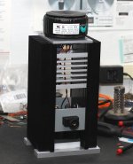
Here's my F3: http://www.diyaudio.com/forums/showthread.php?s=&threadid=85590&highlight= The heatsink I'm using is from R-Theta and it's just about right size for one channel
The PCBs have a scoring line and you just break them apart, no saw needed.
Tea-Bag, thanks for your comments on parts selection and matching the JFETs. I'll take a look on Pass' website and get back to you if I need more help.
Peter, thanks for your reply. I'll take a look at the boards once they arrive.
Peter, thanks for your reply. I'll take a look at the boards once they arrive.
F5 PSU R9/R10
Peter - where do the 2.2K / 3W (R9/R10 in the NP documentation on the F5) resistors fit on the F5 psu boards ?
?
Alan
Peter - where do the 2.2K / 3W (R9/R10 in the NP documentation on the F5) resistors fit on the F5 psu boards
?Alan
I think that R9 and 10 are only meant to be 1/4W - the 3W ones are bleeders used in the power supply.
Fran
Fran
Re: F5 PSU R9/R10
I mount them across the first set of caps on the underside of the PS board.
AlanElsdon said:Peter - where do the 2.2K / 3W (R9/R10 in the NP documentation on the F5) resistors fit on the F5 psu boards
Alan
I mount them across the first set of caps on the underside of the PS board.
Re: Re: F5 PSU R9/R10
Thanks - I will do the same.
Tea-Bag said:
I mount them across the first set of caps on the underside of the PS board.
Thanks - I will do the same.
Sorry alaneldson - I didn't notice "R9/10 from PSU" - yes, just mount them like that on the PS boards.
Fran
Fran
woodturner-fran said:Sorry alaneldson - I didn't notice "R9/10 from PSU" - yes, just mount them like that on the PS boards.
Fran
Fran,
do you have photo showing how did you mount R9/10?
I am having difficulty to find out how/where to install :
- R9/10
- CL60
- and also diodes stated in your recommended BOM.
thanks for posting the earlier BOM. I managed to get all the parts I need for a mono board but haven't started soldering them yet.
OK, not a great photo but see in this pic, I have 2 PS boards (one for each channel in my amp). You can see here how I mounted the diodes using some of Peters PS boards with the diodes on the heatsinks and short wires connecting them to the main PS boards. See at the outside end of each board the resistor (kind of nearly under the heatsink)? Well thats where I put my R9/10.
You can mount the CL60 right at the IEC socket where the AC power comes into the amp. Its mounted in series with the live AC power input. Beware that whereever you mount it, it will get pretty hot, so allow it some space.
hope that helps,
Fran
An externally hosted image should be here but it was not working when we last tested it.
You can mount the CL60 right at the IEC socket where the AC power comes into the amp. Its mounted in series with the live AC power input. Beware that whereever you mount it, it will get pretty hot, so allow it some space.
hope that helps,
Fran
woodturner-fran said:OK, not a great photo but see in this pic, I have 2 PS boards (one for each channel in my amp). You can see here how I mounted the diodes using some of Peters PS boards with the diodes on the heatsinks and short wires connecting them to the main PS boards. See at the outside end of each board the resistor (kind of nearly under the heatsink)? Well thats where I put my R9/10.
You can mount the CL60 right at the IEC socket where the AC power comes into the amp. Its mounted in series with the live AC power input. Beware that whereever you mount it, it will get pretty hot, so allow it some space.
hope that helps,
Fran
Fran...Got it...thanks. It really helps.
Just want to confirm my understanding R9 & R10 are solder to the V+/V- and GND of the PS boards (left hand side of your photo).
And there are 8 diodes or rectifier on each side of your heatsink 🙂
- Status
- Not open for further replies.
- Home
- Group Buys
- F3 and F4 Clone PCB Reissue group buy, also F5 PCBs