Is there a post somewhere that discusses the power supply capacitor and resistor options? Is anyone using Jensen 4 pole capacitors in the power supply? Is there a picture showing which traces to cut for the Jensens? Just curious. Thanks.
Re: four F5 pls
Send me an email as I need your address. Also, each amp board contains 2 channels, so how many channels do you need?
chatziva said:Peter
Can you email me a paypal request for 4 off F5 boards please ?
As for shipping costs, I am in the UK.
Send me an email as I need your address. Also, each amp board contains 2 channels, so how many channels do you need?
orthoefer said:Is there a post somewhere that discusses the power supply capacitor and resistor options? Is anyone using Jensen 4 pole capacitors in the power supply? Is there a picture showing which traces to cut for the Jensens? Just curious. Thanks.
This link show some PS board configuration options: http://www.diyaudio.com/forums/showthread.php?postid=1237660#post1237660
As to Jensen 4 pole, it was explained here: http://www.diyaudio.com/forums/showthread.php?postid=1237678#post1237678
I have those caps and plan to test them against Sikorels I'm using presently.
Percy used to have a special on Nichicon Super Through 15,000uF and this is what I successfuly use in F3.
Any other cap should fit on those boards as well. As to resistors, use either 4 x Panasonic 3W or 2 x Mills 5W as powerwise it should be close. The combined parallel value should be approx 0.1R
Boards
Got the F4 boards and the PS boards. Awaiting the F5 boards.
thanks again. Nicely done. Those pictures of your amps are quite extraordinary.
Got the F4 boards and the PS boards. Awaiting the F5 boards.
thanks again. Nicely done. Those pictures of your amps are quite extraordinary.
I received my F3 boards last week and my F5 boards yesterday. They look and feel very well constructed. Now I have to hunt up the Dale CMF50 resistors to fit the F5 boards. Thanks again Peter.
Peter Daniel said:
This link show some PS board configuration options: http://www.diyaudio.com/forums/showthread.php?postid=1237660#post1237660
As to Jensen 4 pole, it was explained here: http://www.diyaudio.com/forums/showthread.php?postid=1237678#post1237678
I have those caps and plan to test them against Sikorels I'm using presently.
Percy used to have a special on Nichicon Super Through 15,000uF and this is what I successfuly use in F3.
Any other cap should fit on those boards as well. As to resistors, use either 4 x Panasonic 3W or 2 x Mills 5W as powerwise it should be close. The combined parallel value should be approx 0.1R
Peter, thanks for tolerating my numerous questions. I know you've posted the reference to the diode options three times now. My power supply boards don't have the bottom silk screen showing where to cut for the Jensen capacitors. Can you show where to cut for the other 2 power supply caps at the opposite end of the board (your photo only shows one end). Earlier, someone expressed concern for the Jensen capacitors' getting too warm. Is this a legitimate concern?
It looks like you have also made provisions for Caddock Cool Pak power film resistors on the PS board. True?
Finally, is there a schematic somewhere that you are referencing for the PS board that you are shipping with the F5 board?
Thanks.
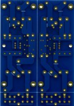
Indeed, the first batch didn't have those lines, only the boards made with F5 order, see attachment.
I also read that caps were getting hot, but didn't test it myself, and should be doing it soon.
Those are not for Caddocks, the board is universal and so suitable for other application, like regulated PS for line stages etc: http://www.audiostereo.pl/zalaczniki/1255687_1.jpg
The populated amp PS board will look like this:
The F3 PS board, being not symmetrical, has provison for even larger, screw type capacitors:
I also read that caps were getting hot, but didn't test it myself, and should be doing it soon.
Those are not for Caddocks, the board is universal and so suitable for other application, like regulated PS for line stages etc: http://www.audiostereo.pl/zalaczniki/1255687_1.jpg
The populated amp PS board will look like this:
An externally hosted image should be here but it was not working when we last tested it.
The F3 PS board, being not symmetrical, has provison for even larger, screw type capacitors:
An externally hosted image should be here but it was not working when we last tested it.
Attachments
Work to date:
Anyone see anything wrong with this, do let me know!
Fran
An externally hosted image should be here but it was not working when we last tested it.
Anyone see anything wrong with this, do let me know!
Fran
woodturner-fran said:Work to date:
An externally hosted image should be here but it was not working when we last tested it.
Anyone see anything wrong with this, do let me know!
Fran
I see some nice square holes in the back. Nice job!
I would like to know how you did that...
woodturner-fran said:Work to date:
An externally hosted image should be here but it was not working when we last tested it.
Anyone see anything wrong with this, do let me know!
Fran
Beautiful. Dual mono including the transformers. Nice. Do the rectifier diodes make that much heat to need that much heatsink?
samoloko said:can you post how to modify PSU pcb to work with ct transformer
The modification would be similar to what I described here: http://www.diyaudio.com/forums/showthread.php?postid=1196283#post1196283
I realized that the holes on the PS board that I thought were interchangable for metal tab resistors are actually for regulators after I studied the board more carefully. Brilliant design. Kudos to you. Thanks for the clarification on the board modifications. Nice work. I like the idea of using capacitors with screw posts for repairability, but I will likely stay with through hole mount caps for ease of mounting it all. I may wait until there is more info on the Jensens before pulling the trigger.Peter Daniel said:Those are not for Caddocks, the board is universal and so suitable for other application, like regulated PS for line stages etc: http://www.audiostereo.pl/zalaczniki/1255687_1.jpg
The populated amp PS board will look like this:
[The F3 PS board, being not symmetrical, has provison for even larger, screw type capacitors:
[/B]
I will definitely be interested in your findings. Keep us posted.Peter Daniel said:I will be testing Jensens this week and report how they perform.
Second set received
Peter,
Second set of boards received - much faster than the first. They as usual look wonderful.
The F5 amp boards - I take it that I got four channels - I cannot believe that they are that small - almost down to Gainclone / Chip Amp size.
At first I thought I would be building the amps from F1 through to F5 - looks like the reverse may be true.
I like some others have ordered the F5 kits from Tech-Diy - I have no problems with vertical mounting of the resistors - what i would ask is why you chose the resistors you did - sound quality or better layout?
Thanks as always Peter - and as with others thanks to Nelson for allowing us to do these group buys.
ALan
woodturner-fran said:Work to date:
An externally hosted image should be here but it was not working when we last tested it.
Anyone see anything wrong with this, do let me know!
Fran
The BOM .pdf that you have uploaded have the small corrections to get all the components fit perfectly in the boards?
No, the BOM PDF for the F5 has all CMF55 type resistors. If you want to use them, you will need to stand them up as I did in the pics a little bit back up.
Haven't had time to go back and change this BOM.... and seeing as I already have mine just about built, I hardly will go back to it either.
******************************
Peter...... whats your opinion with the gate resistors (R13-14) when using the flying wires? Should I just put in a wire link for R13 and 14 and then mount the resistor right on the gate of the mosfet or leave it as is on the PCB. Wires are about 2-3" long.
Fran
woodturner-fran said:No, the BOM PDF for the F5 has all CMF55 type resistors. If you want to use them, you will need to stand them up as I did in the pics a little bit back up.
Haven't had time to go back and change this BOM.... and seeing as I already have mine just about built, I hardly will go back to it either.
******************************
Peter...... whats your opinion with the gate resistors (R13-14) when using the flying wires? Should I just put in a wire link for R13 and 14 and then mount the resistor right on the gate of the mosfet or leave it as is on the PCB. Wires are about 2-3" long.
Fran
Ok, thanks too much, btw, all the res in your BOM are CMF55? i really will be lost if try to modify all the resistors for CMF50 😀 i never purchased at Digikey or Mouser, im sure that will purchase wrong resistors if try to modify that :S
- Status
- Not open for further replies.
- Home
- Group Buys
- F3 and F4 Clone PCB Reissue group buy, also F5 PCBs