My F5 boards arrived today, many thanks Peter. Thats means all of them are here now.
Mucho gracias.
Fran
Mucho gracias.
Fran
Ok fellas I have a problem... or to correctly state it, you may have a problem.
A while back I posted a BOM from mouser for the F3 and F5. Quite a few people have asked me for it or downloaded it from the Peter Daniel F3/F4/F5 thread. There is an issue though that should be noted.
1) The 1/4W resistors won't lie completely flat against the PCB - you would need much smaller ones to do that. Not mission abort stuff, but be aware that you may need to stand them up, which is what I did.
**********************************
Also, somehow I ordered 47k instead of 47R for R13 and R14. The BOM is correct so no biggie there. I have only some very crappy carbon film 1/8W 47R here or a good number of nice Dale 100R. Which should I go with?
Fran
A while back I posted a BOM from mouser for the F3 and F5. Quite a few people have asked me for it or downloaded it from the Peter Daniel F3/F4/F5 thread. There is an issue though that should be noted.
1) The 1/4W resistors won't lie completely flat against the PCB - you would need much smaller ones to do that. Not mission abort stuff, but be aware that you may need to stand them up, which is what I did.
**********************************
Also, somehow I ordered 47k instead of 47R for R13 and R14. The BOM is correct so no biggie there. I have only some very crappy carbon film 1/8W 47R here or a good number of nice Dale 100R. Which should I go with?
An externally hosted image should be here but it was not working when we last tested it.
An externally hosted image should be here but it was not working when we last tested it.
Fran
It has previously been noted that the lead spacing of the resistors was 0.2", and that Peter recommended Vishay CFM-50 or Caddock MK132 resistors, both of which have 0.2" lead spacing. The Dales you use there are CFM-55s (or their military equivalent).
-j
-j
Diomedian said:It has previously been noted that the lead spacing of the resistors was 0.2", and that Peter recommended Vishay CFM-50 or Caddock MK132 resistors, both of which have 0.2" lead spacing. The Dales you use there are CFM-55s (or their military equivalent).
-j
Mounting vertically is common practice on Peter's F4 boards, for those that want some flexibility in resistors used.
Diomedian: I did not pick up that info, obviously missed here, even though i have read this thread easily 3 times now.
BTW, just so we're clear - absolutely no criticism was here implied, I have ordered enough stuff from Peter before now to be well aware that the problem is always mine🙄 . I just wanted to let those who had used my BOM know about it thats all. Lotsa folks might not notice CMF55 vs. CMF50 is all.
Fran
F3 board will accept regular size resistors. With F4 and F5 I'm using Dale CMF50: http://dkc3.digikey.com/PDF/C091/P1890.pdf
If you want to fit regular size resistors, just install them vertically, that shouldn't make any difference.
If you want to fit regular size resistors, just install them vertically, that shouldn't make any difference.
As to the PS boards, please see this link: http://www.diyaudio.com/forums/showthread.php?postid=1237660#post1237660
Re: F5
They would work with some modification.
Yes, I have plenty of them.
samoloko said:can F5 PSU pcbs work with center tapped transformers
They would work with some modification.
chatziva said:Hi Peter,
Do you have any spare F5 boards?
I would be interested in 4 off
Yes, I have plenty of them.
Issues with the Tech-DIY.com parts kit for F5
Peter,
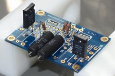
I see where your F5 board has an extra pad for a radial R11 0.47 ohm resistor, but I don't see where the extra pad is for a radial R12 0.47 ohm resistor (see photo).
Next, the two trimmers that I received from Tech-DIY.com have staggered leads, one of which must be bent to fit the current hole pattern on the board. Plus, the axial resistors supplied are very nice Dale pieces, but they must be "stood up" to fit. To me this make it look particularly amateurish. Finally, the Tech-DIY.com F5 kit substitutes 50 ohm Dale resistors for R5&R7 as well as for R6&R8. This huge resistor must also be "stood up" on the board. However its leads are about the same diameter as the holes. The fit is extremely tight. Users may need to drill out the holes to get both leads in the board. Other than that everything is fine--sarcasm.
If you are particular about things like me, do not buy the Tech-DIY.com F5 kit expecting to use it with Peter Daniel's F5 boards. The parts quality is high, but the fit is not so good. I won't use the kit, because I want a better appearance. It's my fault, but maybe others can learn from my mistake.
Peter,
I see where your F5 board has an extra pad for a radial R11 0.47 ohm resistor, but I don't see where the extra pad is for a radial R12 0.47 ohm resistor (see photo).
Next, the two trimmers that I received from Tech-DIY.com have staggered leads, one of which must be bent to fit the current hole pattern on the board. Plus, the axial resistors supplied are very nice Dale pieces, but they must be "stood up" to fit. To me this make it look particularly amateurish. Finally, the Tech-DIY.com F5 kit substitutes 50 ohm Dale resistors for R5&R7 as well as for R6&R8. This huge resistor must also be "stood up" on the board. However its leads are about the same diameter as the holes. The fit is extremely tight. Users may need to drill out the holes to get both leads in the board. Other than that everything is fine--sarcasm.
If you are particular about things like me, do not buy the Tech-DIY.com F5 kit expecting to use it with Peter Daniel's F5 boards. The parts quality is high, but the fit is not so good. I won't use the kit, because I want a better appearance. It's my fault, but maybe others can learn from my mistake.
An externally hosted image should be here but it was not working when we last tested it.
An externally hosted image should be here but it was not working when we last tested it.
An externally hosted image should be here but it was not working when we last tested it.
An externally hosted image should be here but it was not working when we last tested it.
orthoefer: See my post back up a little. I bought those same CMF55 size resistors but directly from mouser, not through tech-diy. You can make them look a little neater (well in my opinion anyway) if you stand them straight up like in my pic above.
You could also mount the bigger 50R ones in a similar way. A little of teh smallest size of heatshrink on the bare wire lead leaves a fairly neat job.
I know what you mean. See a few posts back up on this page about me missing Peters recommendation for the CMF50 size rather than CMF55.
No reason to ditch the kit I think. In fact I'm sure someone here would use it if you don't.. 🙂
Fran
Attached picture shows placement of radial resistors: R12 requires a bit of pin bending and it's due to Q5 being 180 deg opposite to Q3 so the V- supply pin is now further away and I couldn't place the pad las on the other side.
You can still install Dale power resistors normal way, just fold the pins over the PCB edge and solder them underneath. That also reguires attaching output wire underneath the board.
However, the board was designed mainly with a thought of 3W Panasonics or 5W Mills.
As to small resistors, there absolutely shouldn't be a problem placing them vertically, especially when you already using radial power resistors.
Bending the pins on trimmers shouldn't be a big deal either, I did it many times before. It's still nothing compared to complete amps done p2p 😉
http://www.diyaudio.com/forums/showthread.php?s=&threadid=4018&highlight=
http://www.diyaudio.com/forums/showthread.php?s=&threadid=3840&highlight=
Attachments
I belive I recive my PCB ;-)
they arive at my parents adress so I didn't have chance to check them, but I belive everything is fine ;-)
Thanks Peter and one big to Nelson
they arive at my parents adress so I didn't have chance to check them, but I belive everything is fine ;-)
Thanks Peter and one big to Nelson
- Status
- Not open for further replies.
- Home
- Group Buys
- F3 and F4 Clone PCB Reissue group buy, also F5 PCBs